Intake manifold and manufacturing method thereof
a manufacturing method and intake manifold technology, applied in the field of intake manifolds, can solve the problems of inability to integrate with the shell, large number of parts, and higher manufacturing cost, and achieve the effects of reducing the number of parts or the number of assembling processes, reducing manufacturing costs, and allowing sufficient freedom in the design location
- Summary
- Abstract
- Description
- Claims
- Application Information
AI Technical Summary
Benefits of technology
Problems solved by technology
Method used
Image
Examples
embodiment 1
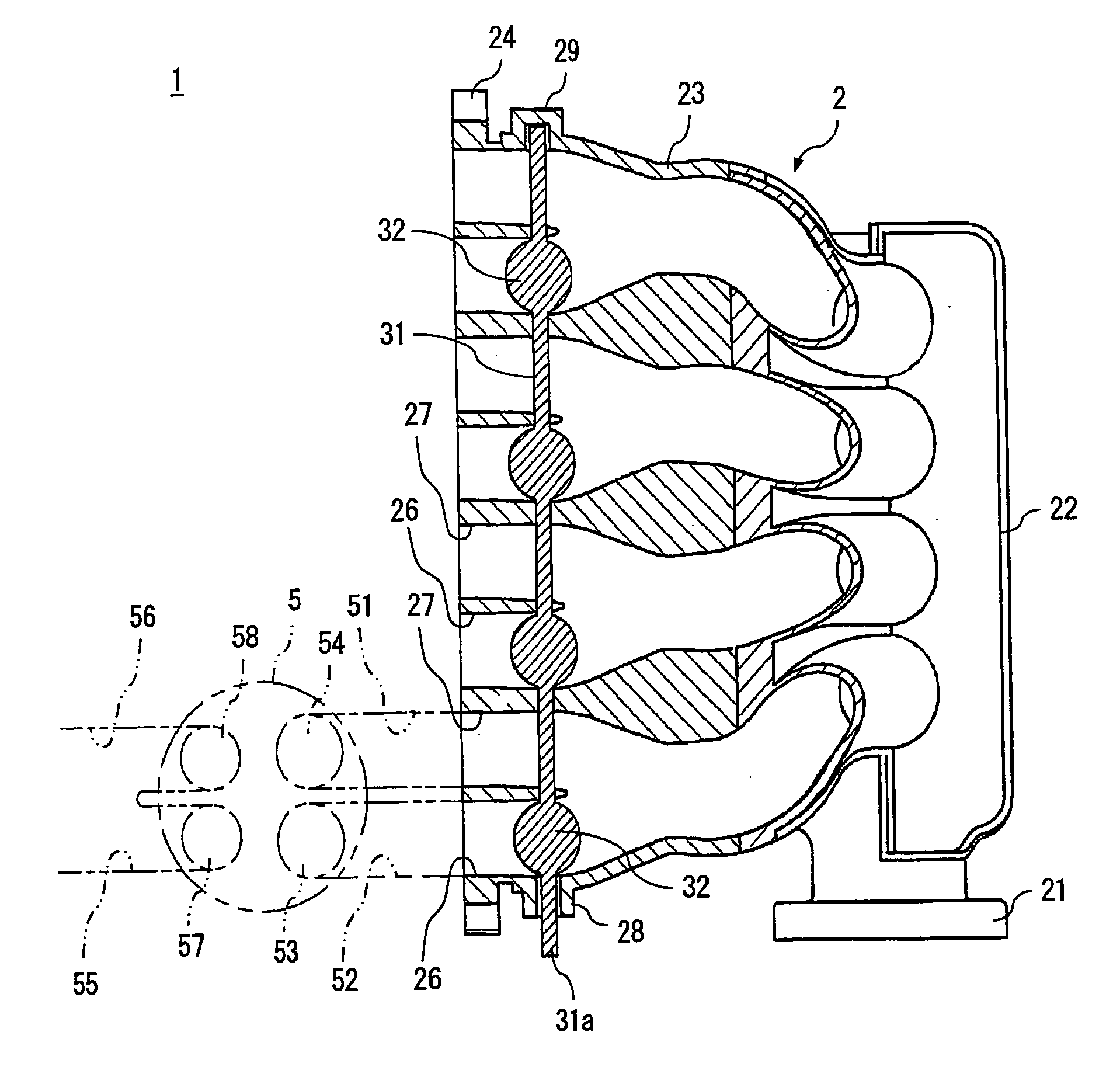
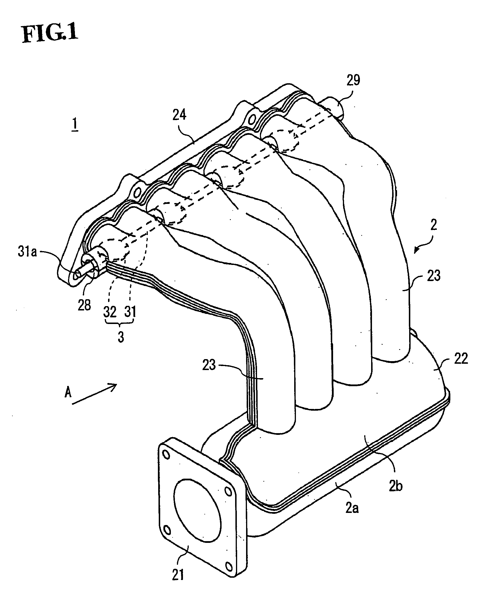
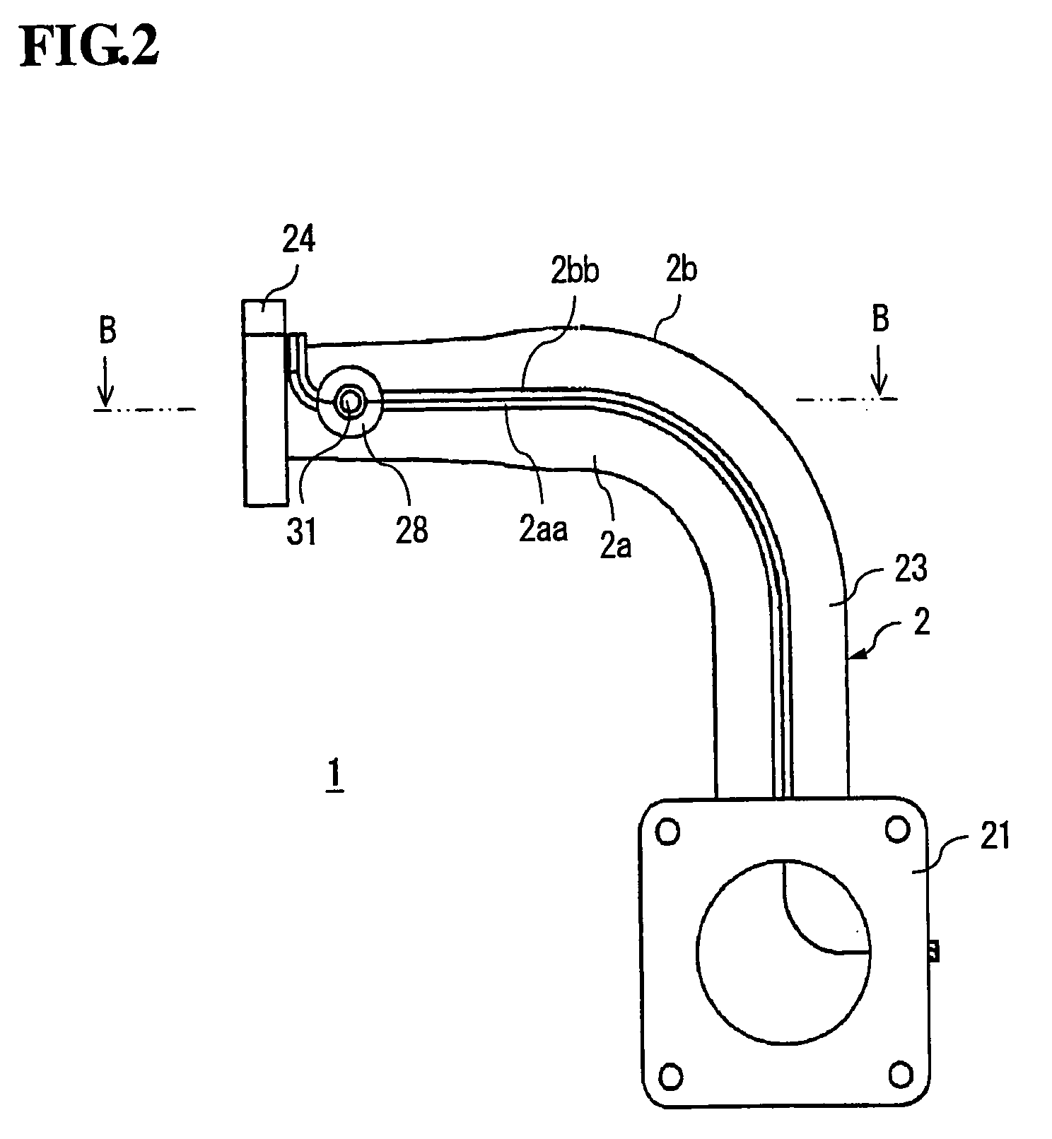
[0024]FIG. 1 is a perspective view of an intake manifold having an intake control valve according to a first preferred embodiment of the invention; FIG. 2 is a side view taken in the direction of the arrow A of FIG. 1; FIG. 3 is a cross sectional view taken along the line B-B of FIG. 2; and FIG. 4 is a perspective view of an intake control valve.
[0025] Referring now to FIGS. 1 to 4, an intake manifold having an intake control valve according to a first preferred embodiment of the present invention is hereinafter described.
[0026] An intake manifold 1 according to this first embodiment is mounted onto an engine head of the so-called four-valve engine in which four valves are disposed with respect to cylinders of an internal combustion engine. The intake manifold 1 includes a hollow shell 2.
[0027] This shell 2 is made of a synthetic resin such as nylon in consideration of heat resistance, strength, and cost. In the shell 2, there are provided a flange 21 for mounting the shell 2 ont...
embodiment 2
[0040]FIG. 6 is a perspective view showing a state in which an intake control valve is set on one of the half bodies before joining the half bodies together in an intake manifold having an intake control valve according to a second embodiment of the invention. FIG. 7 is a partially enlarged cross sectional view taken at the plane C through a center of a shaft 31 of FIG. 6. The same reference numerals indicate components corresponding to those of the foregoing first embodiment shown in FIGS. 1 through 5.
[0041] Features of the intake manifold according to this second embodiment consist in that bearings 41 are disposed in the cylindrical-shaped supports 28, 29 that are formed at the lateral ends of the shell 2 respectively, and that both ends of the shaft 31 are inserted through each bearing 41 to be supported rotatably with the bearings 41. As a material of the bearing 41, any hard resin such as Teflon (trade mark) or metal can be used. In this example, when the intake control valve ...
embodiment 3
[0044]FIG. 8 is a partially enlarged perspective view showing a state in which an intake control valve is set on one of the half bodies before joining the half bodies together in an intake manifold having an intake control valve according to a third embodiment of the invention. FIG. 9 is a partially enlarged cross sectional view taken at the plane D through a center of a shaft of FIG. 8. The same reference numerals refer to components corresponding to those of the foregoing first embodiment shown in FIGS. 1 through 5.
[0045] In the same manner as in the foregoing second embodiment, features of the intake manifold according to the third embodiment consist in that bearings 41 are provided in the cylindrical-shaped supports 28, 29 that are formed in lateral ends of shell 2, and that both ends of the shaft 31 are rotatably supported with each bearing 41. According to this third embodiment, one end of the shaft 31 of the intake control valve 3 is protruding outward from the shell 2 for t...
PUM
| Property | Measurement | Unit |
|---|---|---|
| composition | aaaaa | aaaaa |
| pressure | aaaaa | aaaaa |
| torque performance | aaaaa | aaaaa |
Abstract
Description
Claims
Application Information
 - R&D
- Intellectual Property
- Life Sciences
- Materials
- Tech Scout
- Unparalleled Data Quality
- Higher Quality Content
- 60% Fewer Hallucinations
Browse by: Latest US Patents, China's latest patents, Technical Efficacy Thesaurus, Application Domain, Technology Topic, Popular Technical Reports.
© 2025 PatSnap. All rights reserved.Legal|Privacy policy|Modern Slavery Act Transparency Statement|Sitemap|About US| Contact US: help@patsnap.com


