High output heating device

a heating device and high output technology, applied in the field of high output, multifuel, domestic heating devices, can solve the problems of adversely affecting the output of the device, complex and inefficient techniques for fixing parts, and drawbacks in assembly methods, so as to achieve high output and reduce consumption

Inactive Publication Date: 2005-12-22
THERMIC INVESTMENTS
View PDF9 Cites 19 Cited by
  • Summary
  • Abstract
  • Description
  • Claims
  • Application Information

AI Technical Summary

Benefits of technology

[0027] As a particular advantage, the outer hood is formed by the combustion chamber itself. The sealed feature of the combustion chamber of the device according to the invention allows to achieve a very high output, of the order of even 80% for heating with wood, which is a considerable advantage to those skilled in the art and / or to the user (reduced consumption).

Problems solved by technology

The fixing of the parts is achieved by complex and inefficient techniques making use of tie-rods, throats and putty.
Apart from the loss of productivity, this method of assembly has drawbacks associated with the use of putty.
In fact, when the putty dries, it may shrink or present micro-cracks, which lets air enter the chamber, thus adversely affecting the output of the device.
The presence of putty makes it difficult to obtain the required seal in accordance with the various standards in force in different countries (e.g.: EPA standards in the US).
Moreover, during transportation of the device after manufacture, flows of putty may appear on visible surfaces, which requires the intervention of expensive after-sales service.
The assembly of the various walls thus proves difficult and the seal of the combustion chamber is not guaranteed.

Method used


Image

  • High output heating device
  • High output heating device
  • High output heating device

Examples


Embodiment Construction

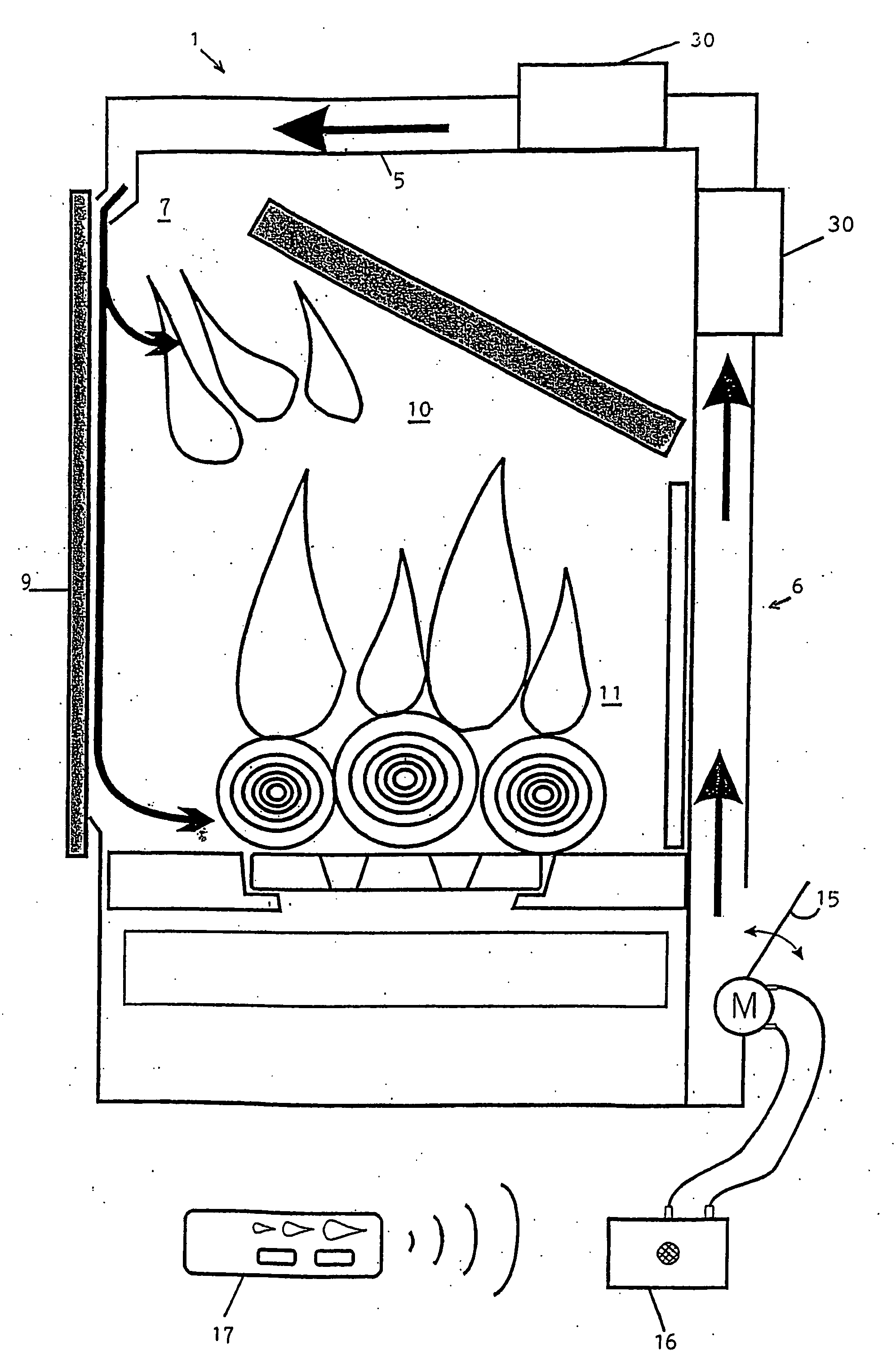
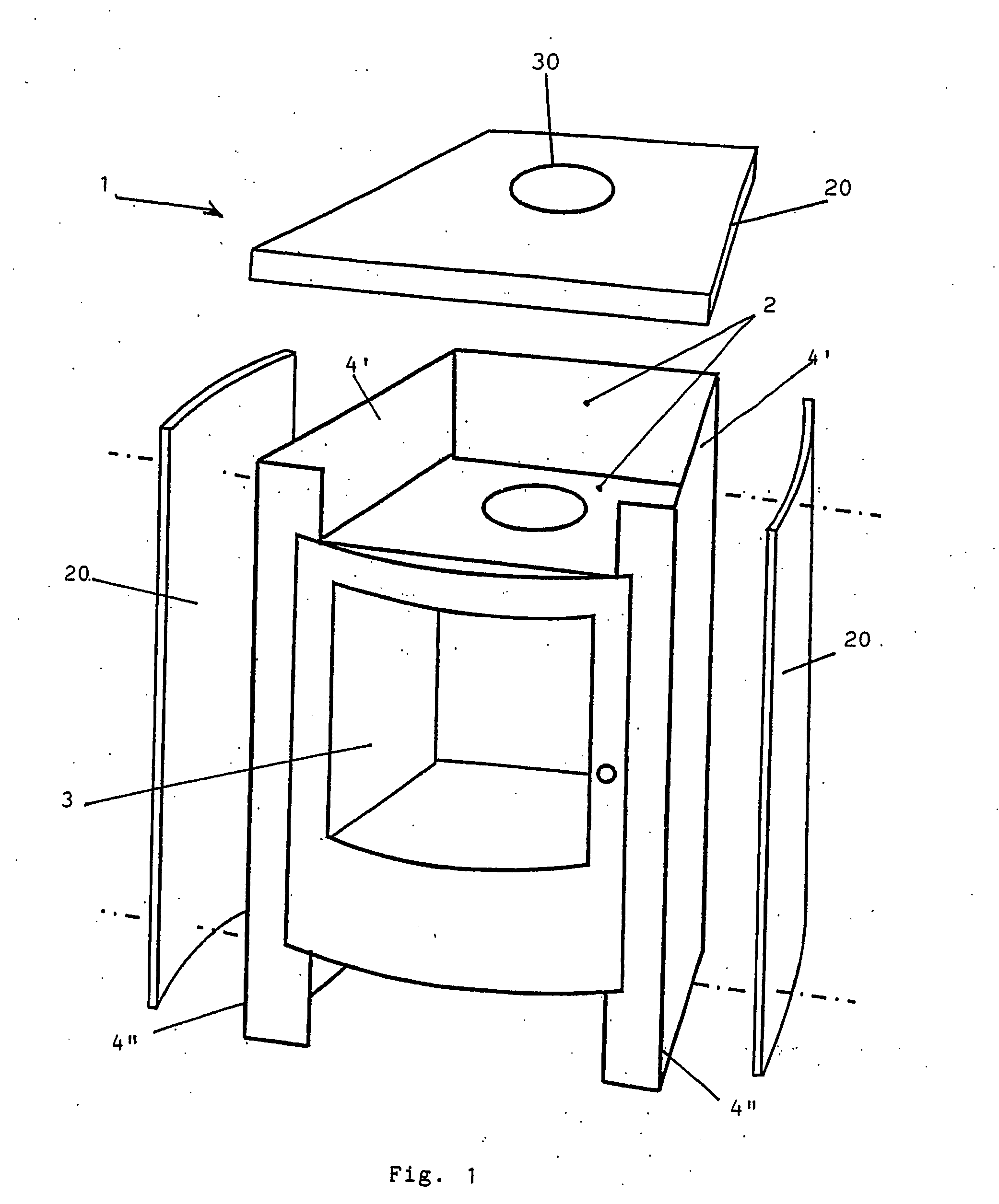
[0039] As described in FIG. 1, the present invention proposes a combustion chamber 1 made of folded and welded sheet steel 2. Alternatively, a different weldable metal could be used. In this way, a combustion chamber is made in a prismatic shape, constructed in accordance with the principle of the “thermos”. The only aperture provided toward the area to be heated is that allowing the placement of a door 3, for instance also in steel or in decorative cast iron, on the front face.

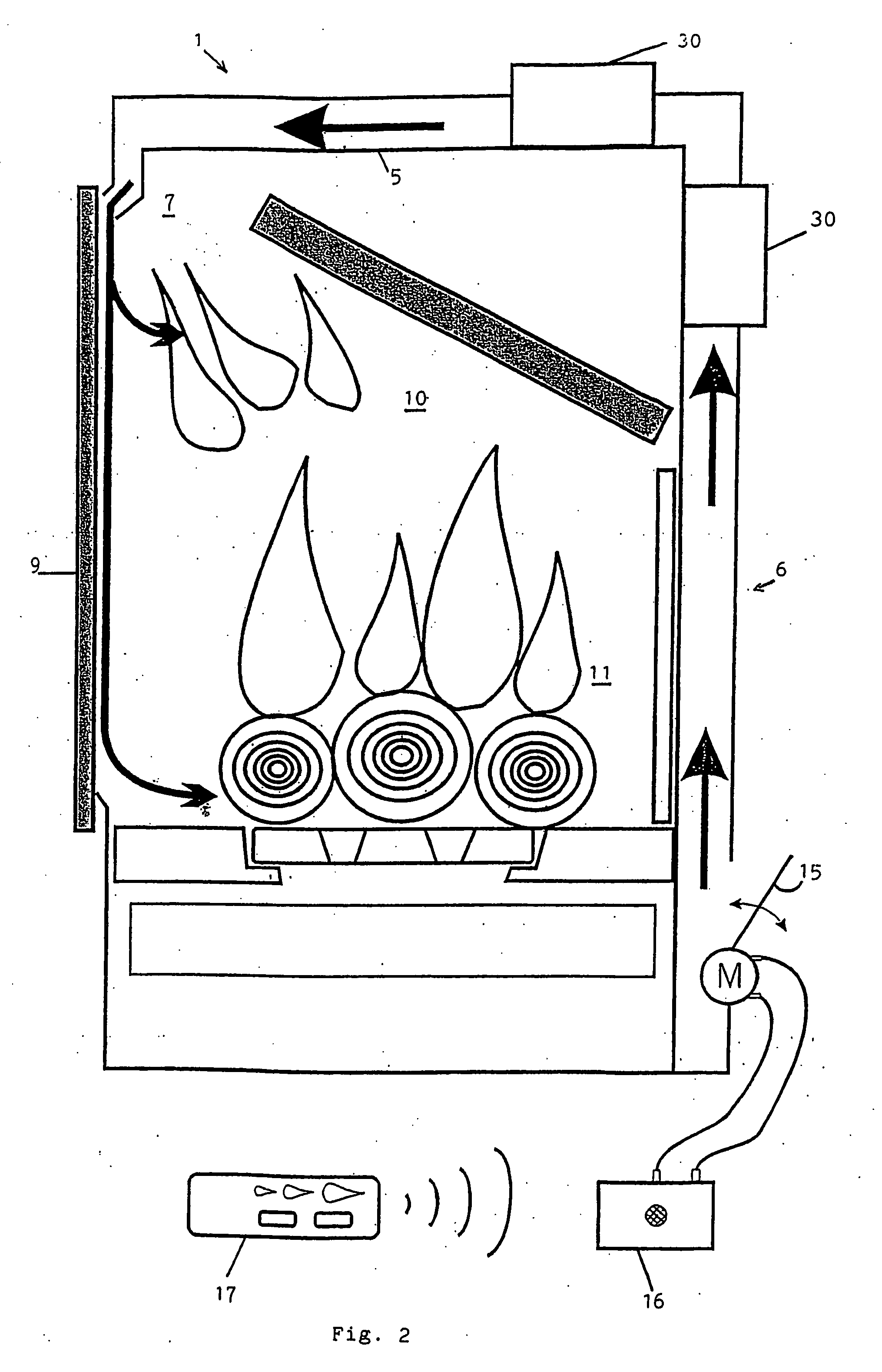
[0040] The principle of a closed combustion chamber according to the invention is a great advantage in as much that the latter may be made in an almost perfectly sealed manner. Slight losses of seal may in fact inevitably occur at the door joint. Therefore, an exceptionally high output is obtained (of the order of 80%). Moreover, the stove or the heating device may comprise only said combustion chamber and have compact dimensions, solely depending on the nominal power desired.

[0041] Advantageously, the heat...


PUM


Abstract

The invention concerns a multiple-fuel heating apparatus wherein: the combustion chamber (1) forms the main support structure of the heating apparatus and is made of sheet metal bent and welded (2) so as to be completely sealed, optionally except at the joint with said door; the elements (20) forming the outer cover are fixed to the combustion chamber, the fixing elements not passing through the chamber and said elements not being necessarily fixed together.

Description

FIELD OF THE INVENTION [0001] The present invention relates to a new concept for high-output, multi-fuel, domestic, heating device comprising a sealed (or almost sealed) heating body whose operation can be remotely controlled. [0002] Sealed heating body should be understood as a heating body whose only communication with the outside consists of an inlet for primary cold air and an outlet for burnt gases. TECHNOLOGICAL BACKGROUND AND STATE OF THE ART [0003] In recent years, major efforts have been undertaken to create “modular” domestic heating devices that have the same shape, design or covering irrespective of the fuel used or of the nominal power required. These different devices are characterised by a combustion chamber (or a heating body) of specific dimensions for a solid, liquid or gaseous fuel or for a specified power level. Thus, the rear wall of the combustion chamber may comprise an intermediate part with an outlet opening adapted to each predefined situation (see patents ...

Claims


Application Information

Patent Timeline
Patent Type & Authority Applications(United States)
IPC IPC(8): F24B1/02F24B13/02
CPCF24B13/02F24B1/028F24B1/02F24B5/025
Inventor CYRIS, RUDY
Owner THERMIC INVESTMENTS
Why Eureka
Try Eureka