
Intelligent driving assistance method and system

a driving assistance and intelligent technology, applied in the direction of pedestrian/occupant safety arrangement, instruments, tractors, etc., can solve the problem that the driver cannot perceive the change in the status of the preceding vehicle in time, and achieve the effect of reducing the operation risk associated

Inactive Publication Date: 2005-12-22
NISSAN MOTOR CO LTD
View PDF3 Cites 18 Cited by
  • Summary
  • Abstract
  • Description
  • Claims
  • Application Information

AI Technical Summary

Benefits of technology

[0007] Various embodiments are disclosed relating to intelligent driving assistance methods and systems that adjust the operation of a vehicle in anticipation of a future decrease of a distance between the vehicle and an object in a field around the vehicle, so as to reduce the operation risk associated with the vehicle.
[0009] According to one embodiment, the data processor determines a trend of the relative speed, and regulates the reaction force based on a change of the trend of the relative speed. According to another embodiment, the relative speed represents a speed of the object relative to the vehicle, and the object is in front of the vehicle. The data processor is configured to initiate an increase of the reaction force applied to the driver control device that is experienced by the driver of the vehicle, in response to the relative speed changing from an increasing relative speed to a non-increasing relative speed. The data processor may further perform the step of responsive to the relative speed decreasing to zero, stopping the increase of the reaction force.

Problems solved by technology

These known systems do not transmit a change in the status of the preceding vehicle to the driver at appropriate timing via the reaction force applied to the accelerator pedal, due to calculation delays by a controller to alter the reaction force and delays in the driver's recognition of the status change caused by the calculation delays.
Consequently, the driver cannot perceive the changed status of the preceding vehicle soon enough via the reaction force applied to the acceleration pedal.

Method used


Image

  • Intelligent driving assistance method and system
  • Intelligent driving assistance method and system
  • Intelligent driving assistance method and system

Examples


first exemplary embodiment

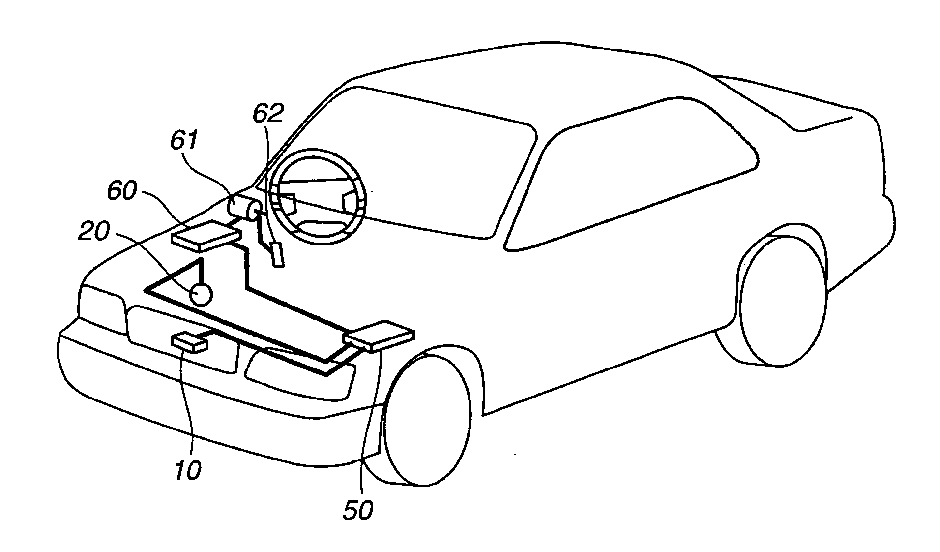
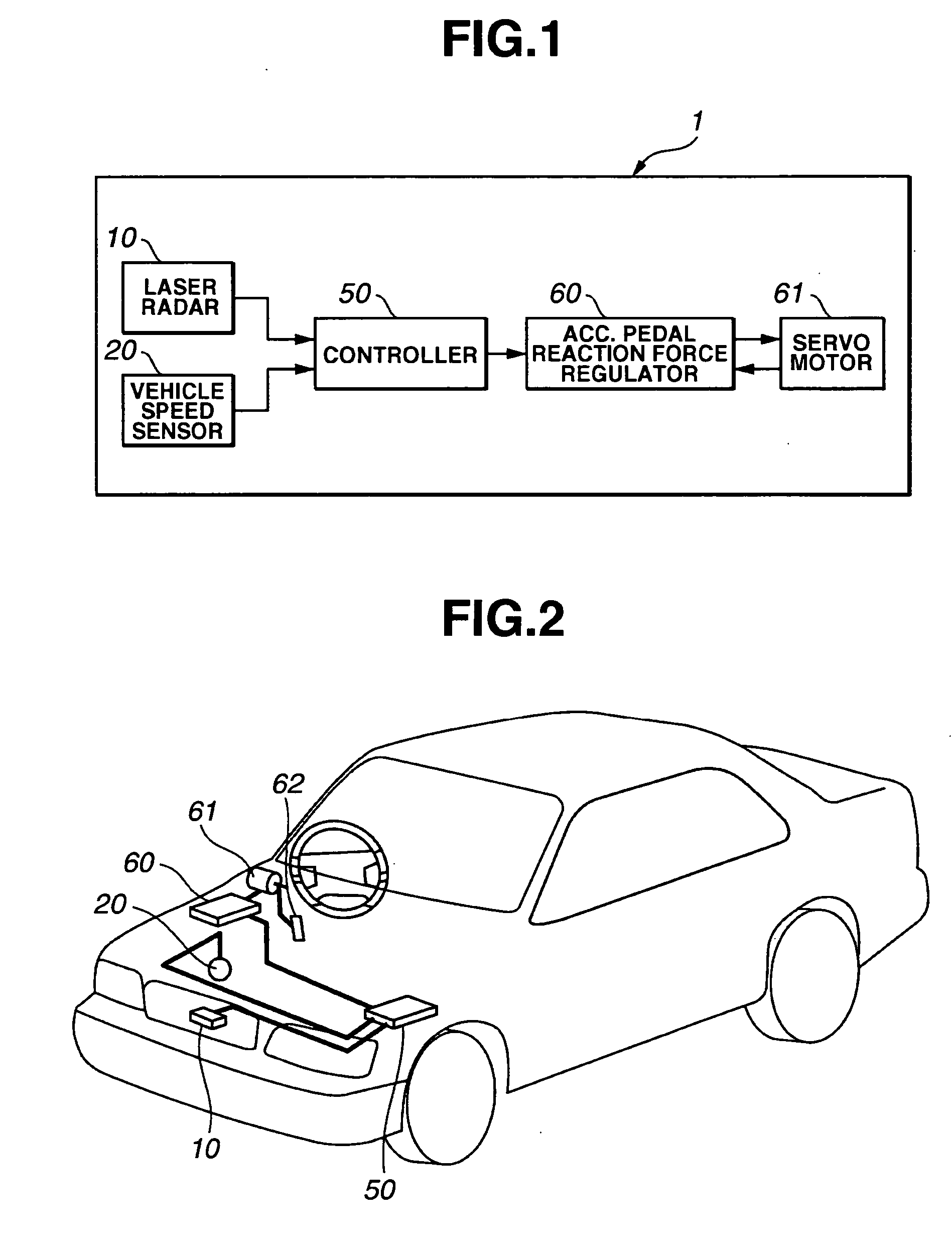
[0034] Referring to FIGS. 1 and 2, the first exemplary embodiment is described. The block diagram in FIG. 1 illustrates the first exemplary embodiment of a system 1 for assisting a driver operating a vehicle traveling on a road. FIG. 2 is a perspective view of a motor vehicle installed with system 1.

[0035] System 1 has a radar 10 positioned at the center of a front grill or a front bumper of a host vehicle (see FIG. 2) for transmitting pulsed beam or radar waves ahead of the vehicle in order to detect obstacles within the field of view of the radar 10. Although it may be a conventional millimeter wave, frequently modulated continuous (FMCW) radar, radar 10, in this embodiment, is a laser-radar. An infrared pulsed beam travels, as a transmitted beam, toward a measurement zone. A light receiving device receives the transmitted beam returning from an obstacle within the measurement zone. Due to the use of a rotating polygonal mirror, two-dimensional scanning in the forward direction i...

second exemplary embodiment

[0099] The second exemplary embodiment is substantially the same as the first exemplary embodiment shown in FIGS. 1 and 2. The second exemplary embodiment is different from the first exemplary embodiment in the manner that decrement and increment corrections of the reaction force control instruction value FA are performed.

[0100] In the first exemplary embodiment, the reaction force control amount FAhosei is subject to the predetermined unit change ΔF and confined within a range having an upper limit of 0 and a lower limit of the minimum value FAmin. Both the predetermined unit change ΔF and the minimum value FAmin are fixed. According to the second exemplary embodiment, a unit change ΔF and a minimum value FAmin are varied with different operation states of host vehicle.

[0101] FIGS. 13 to 16 illustrate the decrement and increment corrections of the reaction force control instruction value FA. The flow chart in FIG. 13 illustrates a sub-routine to be executed at step S540 of the su...


PUM


Abstract

An intelligent driving assistance system for used in a vehicle to convey information related to a future variation of a relative spatial relationship between the vehicle and an object, even before the actual variation occurs. The system includes a detector configured to detect a driving condition of the vehicle and a condition of an object in a field around the vehicle, and a data processor, in anticipation of a future decrease of a distance between the vehicle and the object, regulating a reaction force applied to a driver control device of the vehicle.

Description

RELATED APPLICATION [0001] The present application claims the benefit of priority from Japanese Patent Application No. 2004-177965, filed Jun. 16, 2004, the disclosure of which is incorporated herein by reference in its entirety. FIELD OF THE DISCLOSURE [0002] The present disclosure relates to an intelligent driving assistance method and system for assisting a driver operating a vehicle, and more specifically, to an intelligent driving assistance method and system for use in a vehicle to convey information related to a future variation of a relative spatial relationship between the vehicle and an object, even before the actual variation occurs. BACKGROUND OF THE DISCLOSURE [0003] Various methods and systems were available for assisting a driver to operate a vehicle. One example of such systems is proposed in US 2003 / 0060936 A1, published Mar. 27, 2003 (application Ser. No. 10 / 226,232). This system comprises a controller, at least one actuator, and a data acquisition system for acqui...

Claims


Application Information

Patent Timeline
Patent Type & Authority Applications(United States)
IPC IPC(8): B60K26/02B60K26/04B60K31/00B60R21/00B60W40/02F02D29/02G08G1/16
CPCB60K26/021B60W30/16B60W2550/20B60W50/16B60W40/02B60W2554/00
Inventor KOBAYASHI, YOSUKENAITO, GENPEIKIMURA, TAKESHINISHIDA, YUKINORI
Owner NISSAN MOTOR CO LTD
Learn More