
Paper feeding mechanism and image forming apparatus employing the same

Inactive Publication Date: 2005-12-22
S PRINTING SOLUTION CO LTD
View PDF12 Cites 12 Cited by
  • Summary
  • Abstract
  • Description
  • Claims
  • Application Information

AI Technical Summary

Benefits of technology

[0011] An aspect of the present invention is to solve at least the above problems and / or disadvantages and to provide at least the advantages described below. Accordingly, an aspect of the present invention is to provide a paper feeding mechanism with a simple structure that occupies a smaller space than a conventional paper feeding mechanism.
[0012] Another object of the present invention is to provide a paper feeding mechanism capable of moving a drive roller and a press roller apart from each other without requiring a separate driving means.

Problems solved by technology

This unnecessary force reduces the quality of the printed image.
Therefore, it is difficult to produce a product with a small size and manufacturing costs are increased.
Producing a reliable electronic clutch is very difficult and requires significant costs.
Thus, it is difficult to ensure the reliability of the paper feeding mechanism.

Method used


Image

  • Paper feeding mechanism and image forming apparatus employing the same
  • Paper feeding mechanism and image forming apparatus employing the same
  • Paper feeding mechanism and image forming apparatus employing the same

Examples


Embodiment Construction

[0035] The matters defined in the description such as a detailed construction and elements are provided to assist in a comprehensive understanding of the embodiments of the invention. Accordingly, those of ordinary skill in the art will recognize that various changes and modifications of the embodiments described herein can be made without departing from the scope and spirit of the invention. Also, descriptions of well-known functions and constructions are omitted for clarity and conciseness.

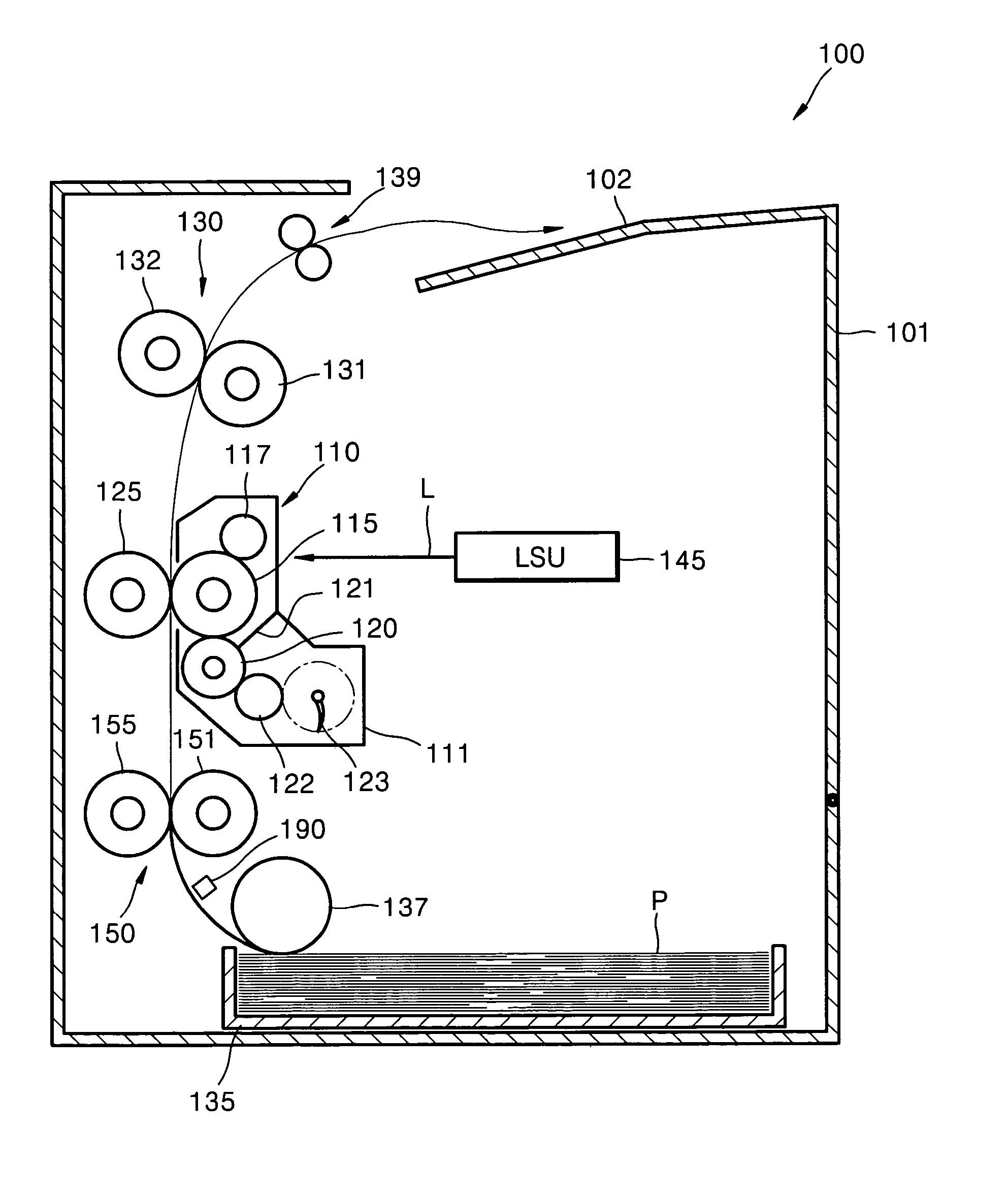
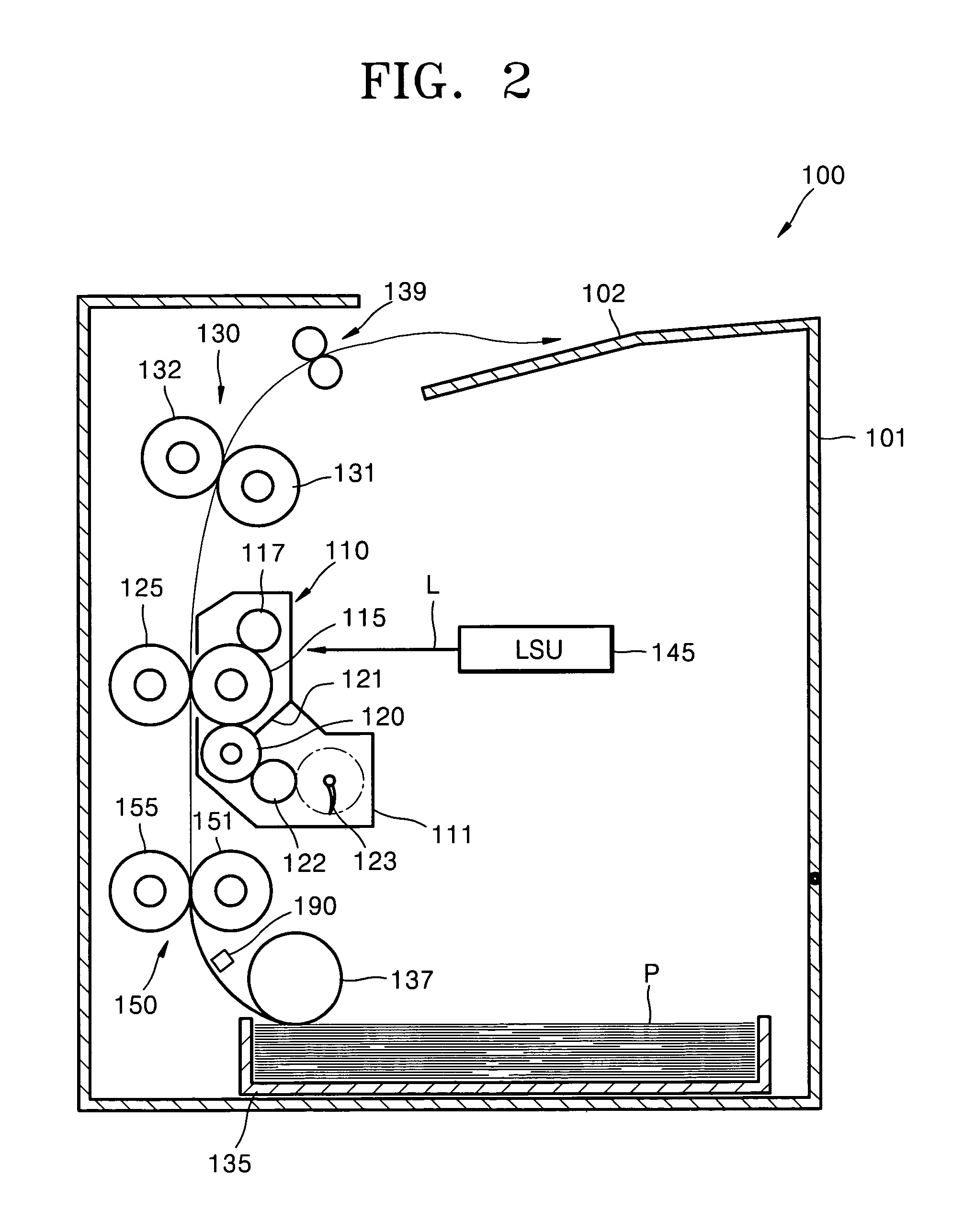
[0036] Referring to FIG. 2, the image forming apparatus 100 in the illustrated embodiment is an electrophotographic image forming apparatus. An electrophotographic image forming apparatus uses a light beam to scan a photosensitive medium charged with a predetermined potential to create an electrostatic latent image. The latent image is developed with a toner of a desired color, and the developed latent image is transferred to and fixed on paper. The image forming apparatus includes a case 101, ...


PUM


Abstract

A paper feeding mechanism for an image forming apparatus includes a drive roller rotated by a first shaft driven by a motor. A press roller is supported by a second shaft which is parallel to and spaced apart from the first shaft. The press roller is pressed against the drive roller, and is driven by the drive roller. A cam pushes the second shaft (and therefore the press roller) away from the drive roller to prevent unnecessary external forces from being exerted on paper being fed through the rollers. The cam is actuated by clutching means for transferring rotating force of the first shaft to the cam to rotate the cam when it is necessary to move the press roller away from the drive roller.

Description

CROSS-REFERENCE TO RELATED APPLICATIONS [0001] This application claims the benefit under 35 U.S.C. § 119(a) of Korean Patent Application Serial No. 2004-44513, filed on Jun. 16, 2004, the entire disclosure of which is hereby incorporated by reference. BACKGROUND OF THE INVENTION [0002] 1. Field of the Invention [0003] The present invention relates to an image forming apparatus. More particularly, the present invention relates to a paper feeding mechanism for an image forming apparatus that includes a drive roller and a press roller which are selectively moved apart from each other to prevent unnecessary external forces from being exerted on paper being fed by the mechanism. [0004] 2. Description of the Related Art [0005] In general, an image forming apparatus is an apparatus for printing a desired image on paper, such as a printer, a copy-machine, and the like. These apparatuses include a printing mechanism for printing an image on paper and a paper feeding mechanism for feeding pap...

Claims


Application Information

Patent Timeline
IPC IPC(8): B65H5/02B65H5/04G03G15/00B65H5/06
CPCB65H5/06B65H1/266B65H3/0684B65H5/064G03G15/6511
Inventor AHN, BYEONG-HWALYU, SE-HYUN
Owner S PRINTING SOLUTION CO LTD
Features
  • Generate Ideas
  • Intellectual Property
  • Life Sciences
  • Materials
  • Tech Scout
  • Unparalleled Data Quality
  • Higher Quality Content
  • 60% Fewer Hallucinations
Learn More