

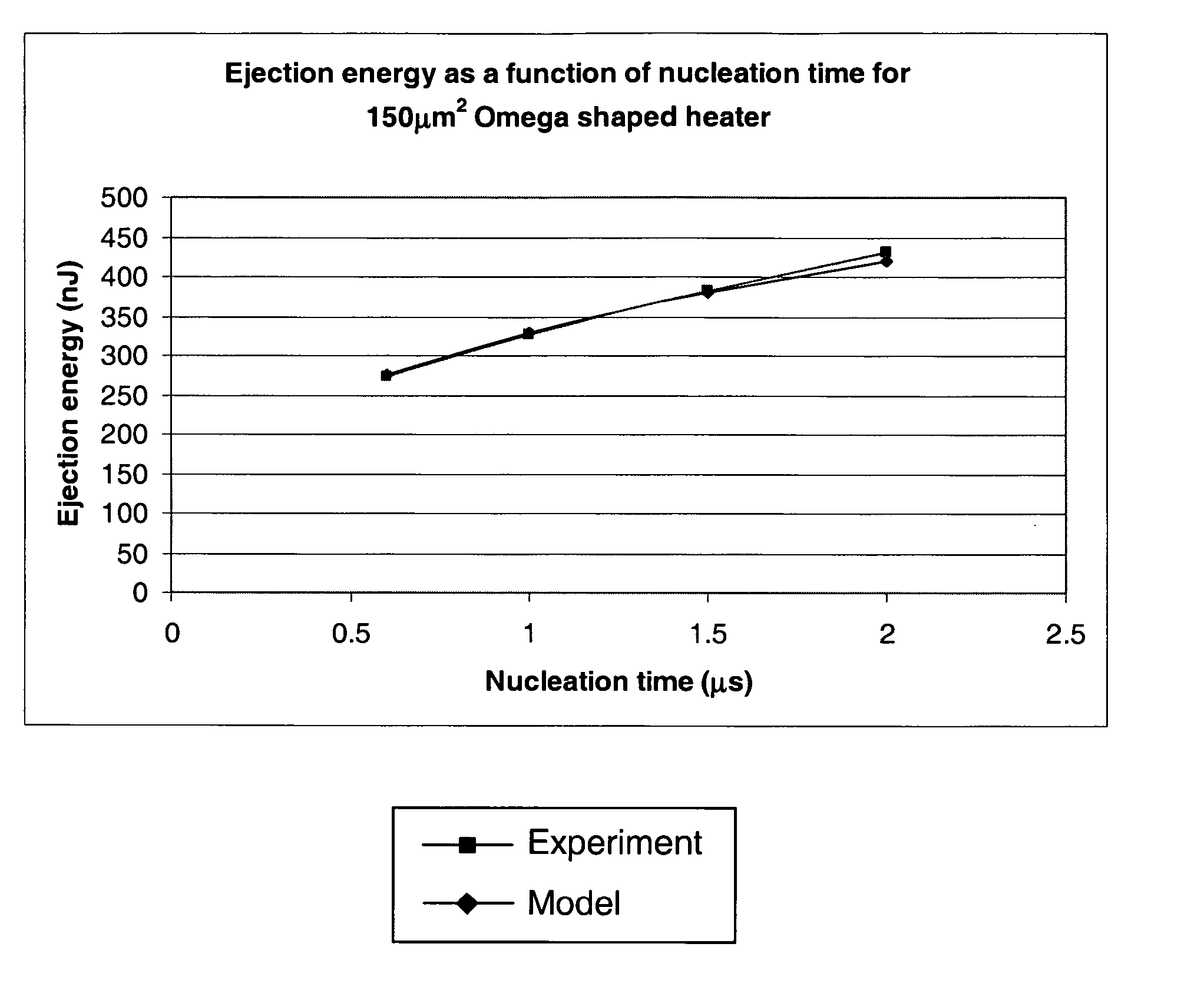
Printhead heaters with short pulse time
a technology of printhead heater and pulse time, which is applied in the direction of printing, etc., can solve the problems of limited geometric packing constraints and nozzle refill rates, and achieve the effects of reducing the energy required for fire, effective solution, and reducing the ejection energy
- Summary
- Abstract
- Description
- Claims
- Application Information
AI Technical Summary
Benefits of technology
Problems solved by technology
Method used
Image

Examples
Embodiment Construction
[0229] In the description than follows, corresponding reference numerals, or corresponding prefixes of reference numerals (i.e. the parts of the reference numerals appearing before a point mark) which are used in different figures relate to corresponding parts. Where there are corresponding prefixes and differing suffixes to the reference numerals, these indicate different specific embodiments of corresponding parts.
Overview of the Invention and General Discussion of Operation
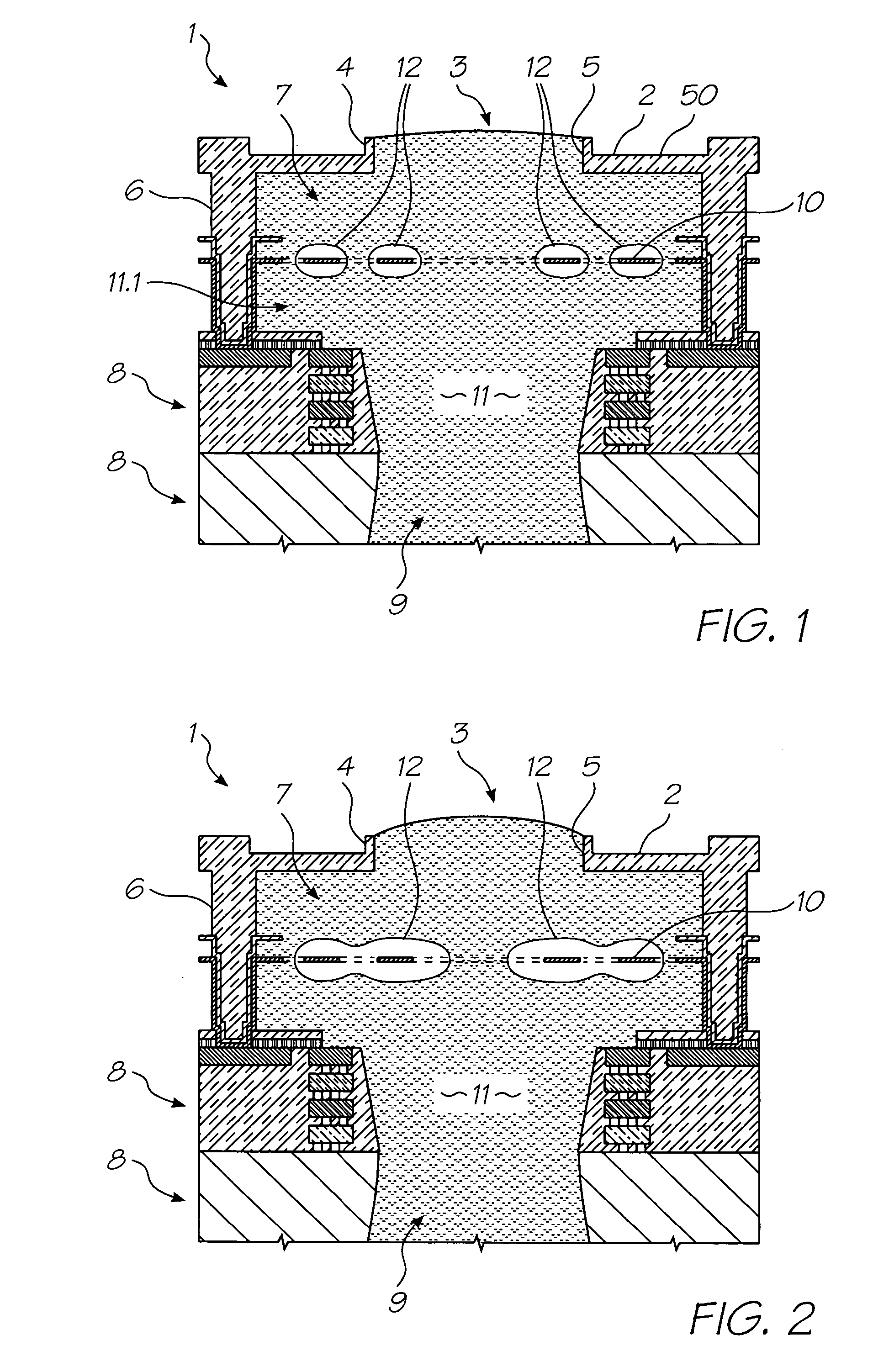
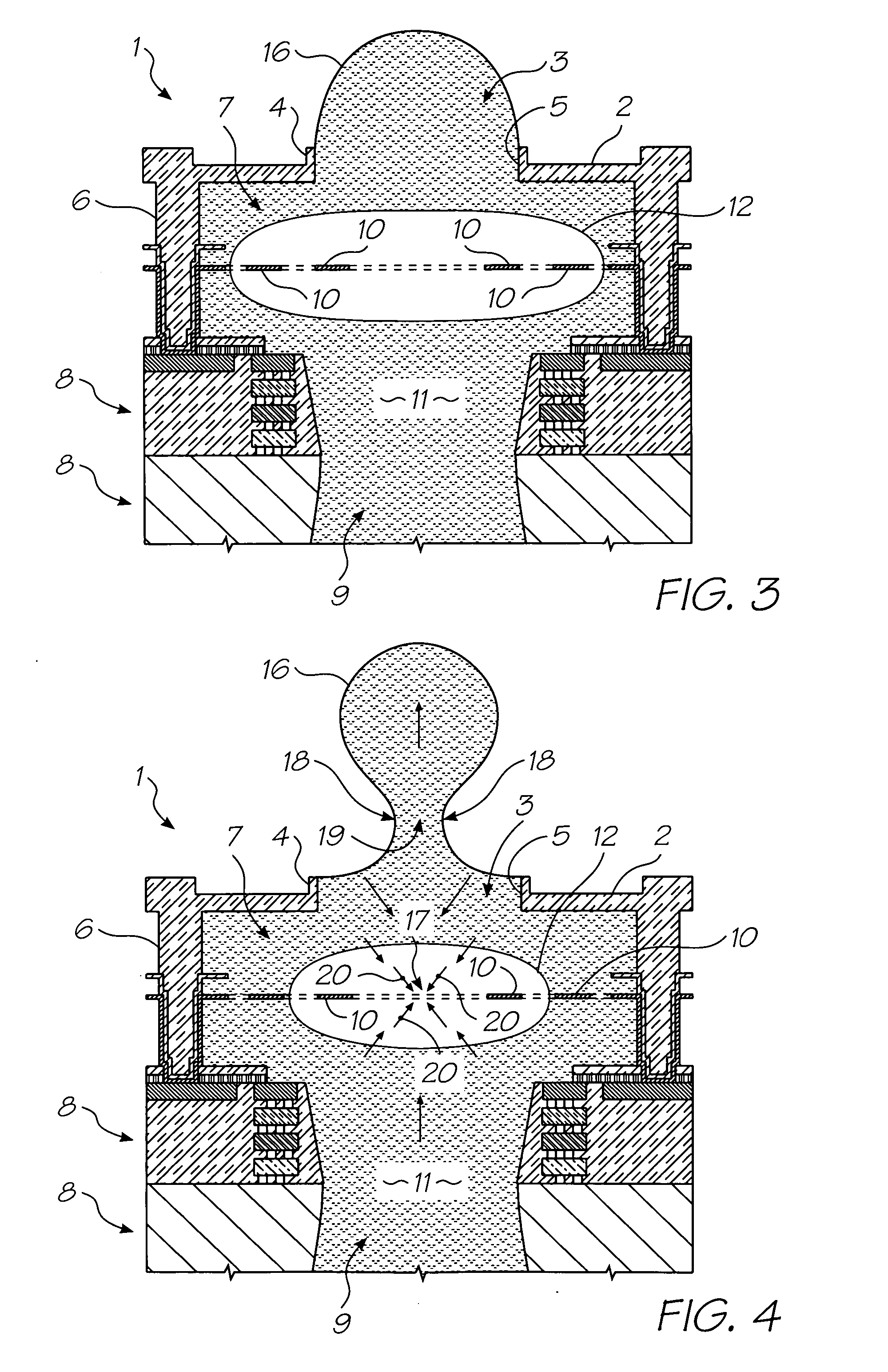
[0230] With reference to FIGS. 1 to 4, the unit cell 1 of a printhead according to an embodiment of the invention comprises a nozzle plate 2 with nozzles 3 therein, the nozzles having nozzle rims 4, and apertures 5 extending through the nozzle plate. The nozzle plate 2 is plasma etched from a silicon nitride structure which is deposited, by way of chemical vapor deposition (CVD), over a sacrificial material which is subsequently etched.
[0231] The printhead also includes, with respect to each nozzle 3, side ...
PUM
 Abstract
Description
Claims
Application Information