
Transparent camera calibration tool for camera calibration and calibration method thereof

a technology of transparent cameras and calibration tools, applied in the field of transparent camera calibration tools for camera calibration and calibration methods thereof, can solve the problems of inability to adapt to outdoor applications or the like, and the fundamental defect of errors accumulating with each successive movement, so as to achieve high-precision multi-view stereo vision, increase reliability, and simplify the time-consuming application of calibration.

Inactive Publication Date: 2005-12-22
JAPAN AEROSPACE EXPLORATION AGENCY
View PDF13 Cites 69 Cited by
  • Summary
  • Abstract
  • Description
  • Claims
  • Application Information

AI Technical Summary

Benefits of technology

[0007] A problem that the present invention is intended to solve is to provide a camera calibration method not requiring the work involved in installing and withdrawing a calibration tool as a preliminary process and which, even when the position and orientation of the camera and the focal length thereof are changed, allows capturing image to be performed by accurately calibrating the camera parameters in accordance with the changes in the position and orientation of the camera and the focal length thereof.

Problems solved by technology

There is also the problem that, because the calibration tool is installed and withdrawn, same is not suited to an outdoor application or the like.
This also entails the fundamental defect that errors accumulate with each successive movement.

Method used


Image

  • Transparent camera calibration tool for camera calibration and calibration method thereof
  • Transparent camera calibration tool for camera calibration and calibration method thereof
  • Transparent camera calibration tool for camera calibration and calibration method thereof

Examples


embodiment example 1

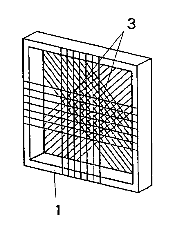
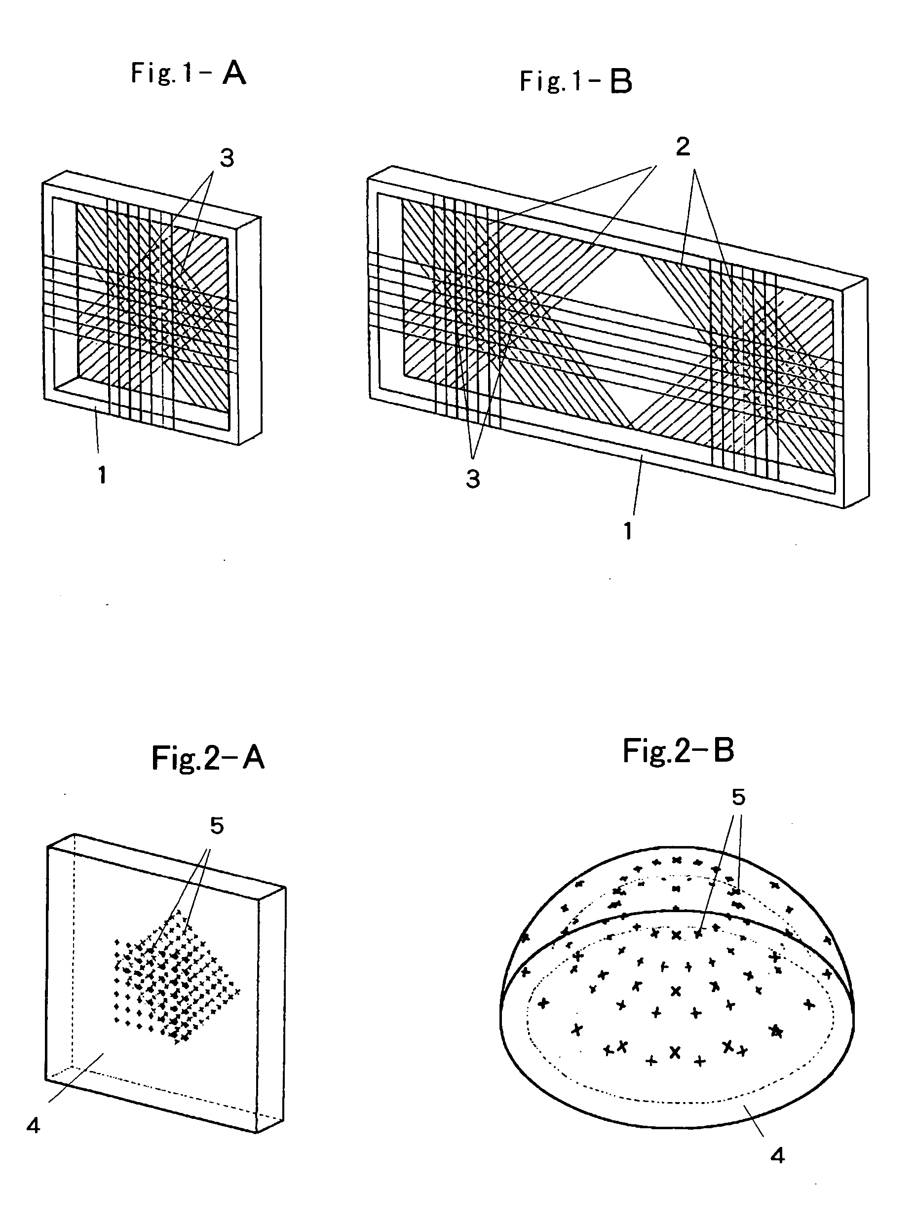
[0080]FIG. 8 shows an embodiment example of a stereo vision transparent camera calibration tool. A rectangular frame is created by integrating two aluminum plates with a breadth dimension 29 cm, vertical dimension of 12 cm and a thickness of 0.5 cm so same are overlapped with a distance of 2 cm between the front face and the rear face, whereupon steel wires with a diameter of 0.083 mm are fixed to one side at 3 cm intervals seven at a time by using adhesive so that the steel wires intersect each other vertically and horizontally, while the same wires are fixed to the other side at 3.54 cm intervals eleven at a time by using adhesive so that the wires are diagonally orthogonal.

embodiment example 2

[0081] Next, an embodiment of a camera calibration system that uses the transparent camera calibration tool of the present invention will be described. The simplest embodiment in terms of equipment is a case where one camera is used. As shown schematically in FIG. 9, in this embodiment, a transparent calibration tool is first installed in a position directly in front of the camera as a processing to capture as shown in the top right of FIG. 9, whereupon a close range transparent calibration tool is imaged by the camera, the image of the calibration tool shown on the center right is obtained, and the image is analyzed, whereby the parameters for the camera position and orientation are calculated and stored. A procedure is adopted in which, a short while afterwards, the camera is made to focus on an object a remote distance therefrom and photographs the object as shown in the top left to obtain an observed image of the object as shown on the center left, whereupon a three-dimensional ...

embodiment example 3

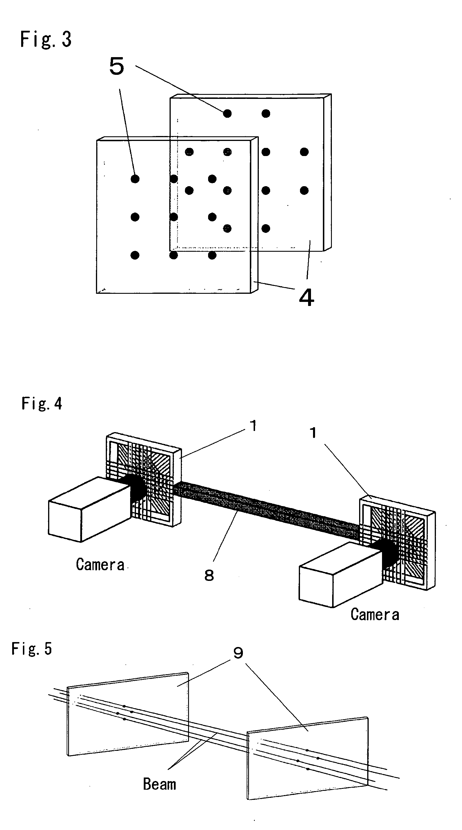
[0082] When two cameras are used, appropriate usage that involves allocating one camera especially to image for calibration acquisition and allocating the other camera especially to observed image can be used as shown schematically in FIG. 10. In this case, readjustment of the focus is unnecessary and, therefore, even in the case of scene image in which a moving body is tracked, an observed image such as that illustrated on the center left and an image of the calibration tool such as that illustrated on the center right can be obtained sequentially in parallel by the observed image camera and the image for calibration acquisition camera respectively, whereupon the images can be analyzed and calibration of the time-varying camera positions and orientation can be performed at the same time as the observed image by calculating the parameters of the camera position and orientation. However, in this embodiment, two cameras must be integrally fixed so that same do not move separately as s...


PUM


Abstract

The calibration tool of the present invention is a transparent camera calibration tool in which a plurality of indicator points is spatially distributed and fixed, wherein the indicator points are formed as intersecting points of thin wires extended to the frame by varying the position of the thin wires in the thickness direction and the indicator points are formed as groups of intersecting points of thin wires rendered by extending a plurality of parallel thin wire groups in different directions. The indicator groups are arranged in at least two sets in a non-coplanar relationship and embodied by distributing distinguishable minute particles in a transparent raw material or by marks or similar in the surface of the raw material. Further, a plurality of cameras arranged separately from one another are calibrated in the same coordinate system by using the transparent camera calibration tool, plate tools that are added thereto, and light beams.

Description

BACKGROUND OF THE INVENTION [0001] 1. Field of the Invention [0002] The present invention relates to a transparent camera calibration tool that is employed in camera calibration of computer vision for estimating parameters of six degrees of freedom (extrinsic parameters) for the position and orientation of a camera and parameters (intrinsic parameters) such as the image center position and lens distortion coefficients, which are camera-specific qualities, and to a geometrical calibration method that employs the transparent camera calibration tool. [0003] 2. Description of the Related Art [0004] In computer vision, the estimation of extrinsic parameters, which express the relationship between a camera coordinate system and a world coordinate system and intrinsic parameters, which express the relationship between an image coordinate system and the camera coordinate system, is indispensable. It is difficult to determine the position and orientation of a camera on the basis of camera sp...

Claims


Application Information

Patent Timeline
Patent Type & Authority Applications(United States)
IPC IPC(8): G01B11/00G01B21/04G01C11/02H04N5/232H04N13/239H04N17/00
CPCG01C11/02H04N13/0246H04N13/0239H04N13/246H04N13/239G01B11/002G06T7/80G01B21/042G01B11/00
Inventor KATAYAMA, YASUHIRO
Owner JAPAN AEROSPACE EXPLORATION AGENCY
Learn More