Heat sink and chip sandwich system

a heat sink and chip sandwich technology, applied in the field of electronic devices, can solve problems such as unwanted fragility loads, and achieve the effect of minimizing the amount of pressur

a heat sink and chip sandwich technology, applied in the field of electronic devices, can solve problems such as unwanted fragility loads, and achieve the effect of minimizing the amount of pressur

US20050281001A1Inactive Publication Date: 2005-12-22GOOGLE LLC

Image

  • Heat sink and chip sandwich system
  • Heat sink and chip sandwich system
  • Heat sink and chip sandwich system

Examples


Embodiment Construction

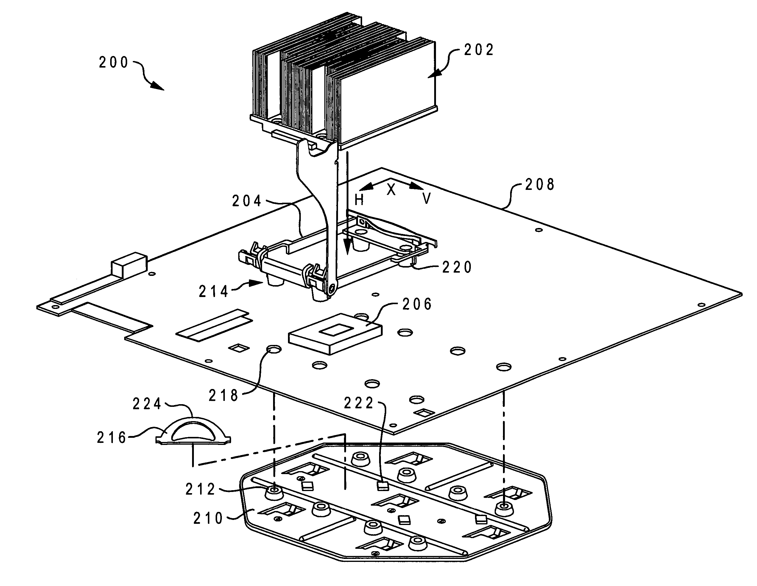
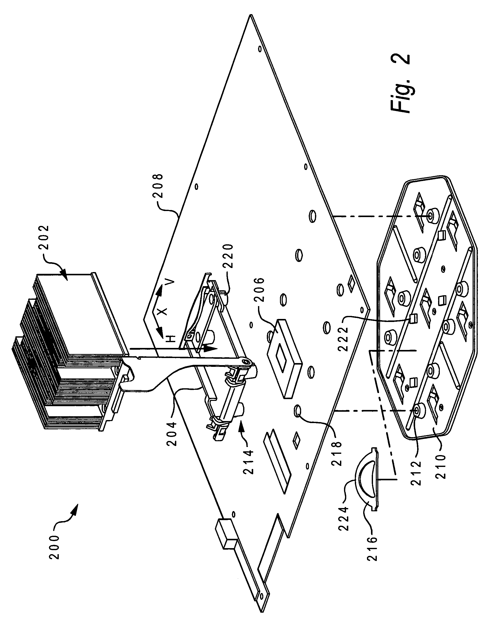
[0020] With reference now to FIG. 2, there is depicted an exploded view of a chip sandwich system 200 in accordance with the present invention. A heat sink 202 is mountable on a retention module 204. Retention module 204 is oriented such that a chip 206 (preferably a Central Processing Unit—CPU chip), which is socket mounted on a circuit board identified as a mother board 208, is in the center of the retention module 204.

[0021] Positioned below mother board 208 is a mounting plate 210. Mounting plate 210 has multiple standoffs 212, which provide two functions. First, standoffs 212 provide a thread for receiving mounting screws that couple retention module legs 214 to standoffs 212, thus resulting in the coupling of retention module 204 with mounting plate 210. Second, standoffs 212 provide a limited gap between mounting plate 210 and a bottom surface of mother board 208, for reasons that will be described below when discussing the function of a wave washer spring 216.

[0022] As dep...


PUM


Abstract

A chip sandwich includes a heat sink, a retention module, a computer chip mounted in a socket on a mother board, a wave washer spring and a mounting plate. The heat sink is mounted on the retention module using cams, hooks and heat sink tabs to provide an initial orientation of the heat sink over the computer chip. To provide final contact pressure between the heat sink and the computer chip, a wave washer spring oriented beneath the computer chip and under the mother board provides an upward pressure against the bottom of the mother board, and particularly against the center of the computer chip. Thus, by the wave washer spring pushing against the center of the computer chip, secure contact pressure is provided between the heat sink and the computer chip, while minimizing the amount of pressure between the computer chip's pins and the chip socket.

Description

BACKGROUND OF THE INVENTION [0001] 1. Technical Field [0002] The present invention relates in general to the field of electronics, and in particular to electronic chips that generate extraneous heat during normal operation. More particularly, the present invention relates to a method and system for conducting heat away from an integrated circuit, which still more particularly may be a microprocessor. [0003] 2. Description of the Related Art [0004] In a typical personal computer (PC), the main heat-generating component among the logic circuits is the processor, also referred to as the Central Processing Unit (CPU) or microprocessor (MP). As illustrated in FIG. 1, a processor 102 is mounted in a socket 104, which is mounted on a (printed) circuit board 106 by mating pins 108 from the processor 102 into the socket 104. As processors continue to grow in performance, so does the heat generated by the processors. To remove heat from processor 102, a heat sink (HS) 110, having a HS base 11...

Claims


Application Information

Patent Timeline
22 Dec 2005
Publication
US20050281001A1
IPC
A44B99/00; H01L23/40; H05K7/20
CPC
H01L23/4093; H01L2924/0002; Y10T24/44017; Y10T24/44026; H01L2924/00
Inventors
DITTUS, KARL KLAUS; FARROW, TIMOTHY SAMUEL