Optical connector system with EMI shielding

a technology of optical connectors and shielding, applied in the field of optical connector systems with electromagnetic interference shielding, can solve the problems of emi becoming a more serious problem, emi control has arisen, and electromagnetic radiation leakage through the opening in the bulkhead or backplan

Inactive Publication Date: 2005-12-22
3M INNOVATIVE PROPERTIES CO
View PDF27 Cites 93 Cited by
  • Summary
  • Abstract
  • Description
  • Claims
  • Application Information

AI Technical Summary

Problems solved by technology

The presence of a physical opening through the bulkhead or backplane of an electronic cabinet creates the potential for electromagnetic radiation leakage through the opening in the bulkhead or backpla...

Method used


Image

  • Optical connector system with EMI shielding
  • Optical connector system with EMI shielding
  • Optical connector system with EMI shielding

Examples


examples

[0041] The improved EMI shielding provided by an optical connector system according to the invention is illustrated in the following example.

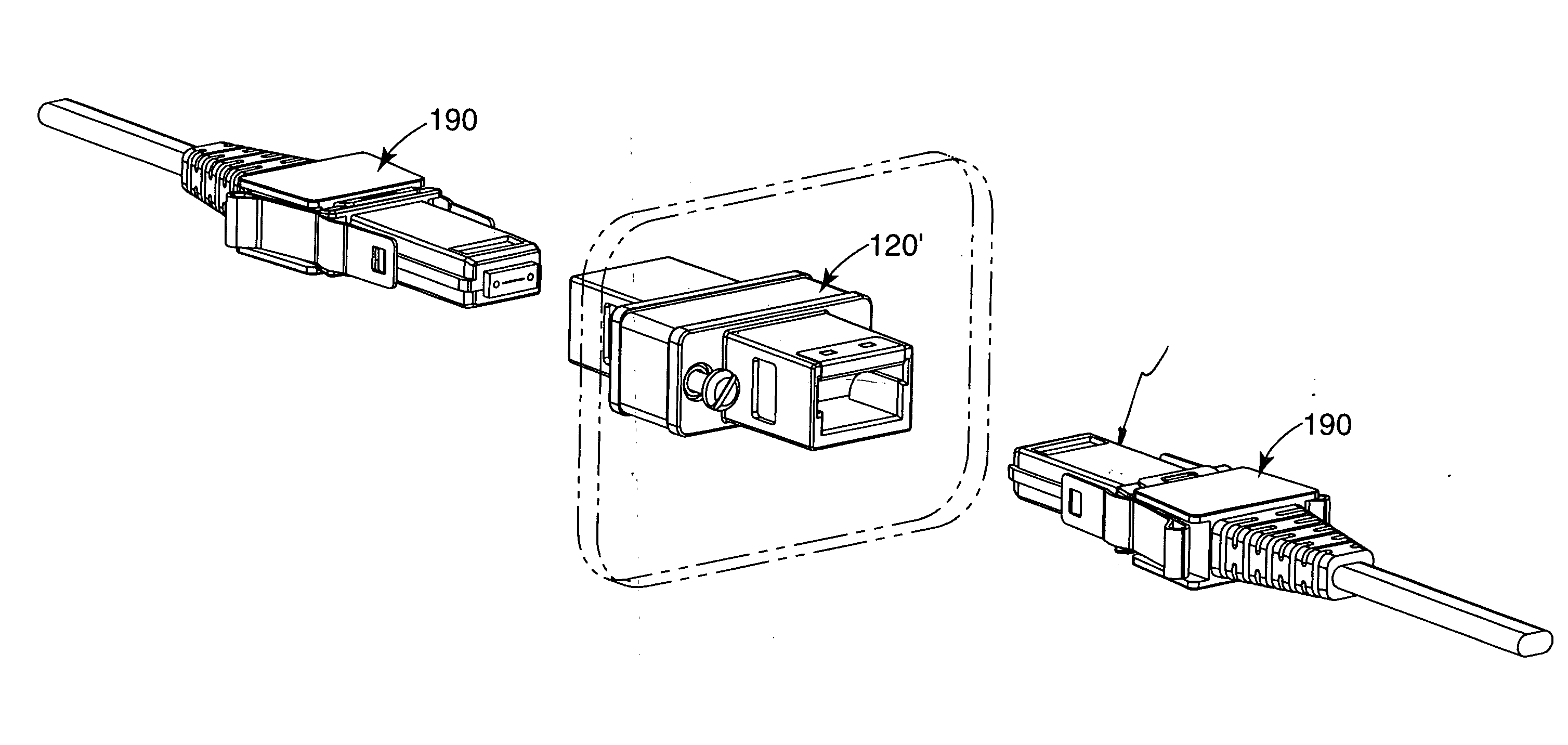
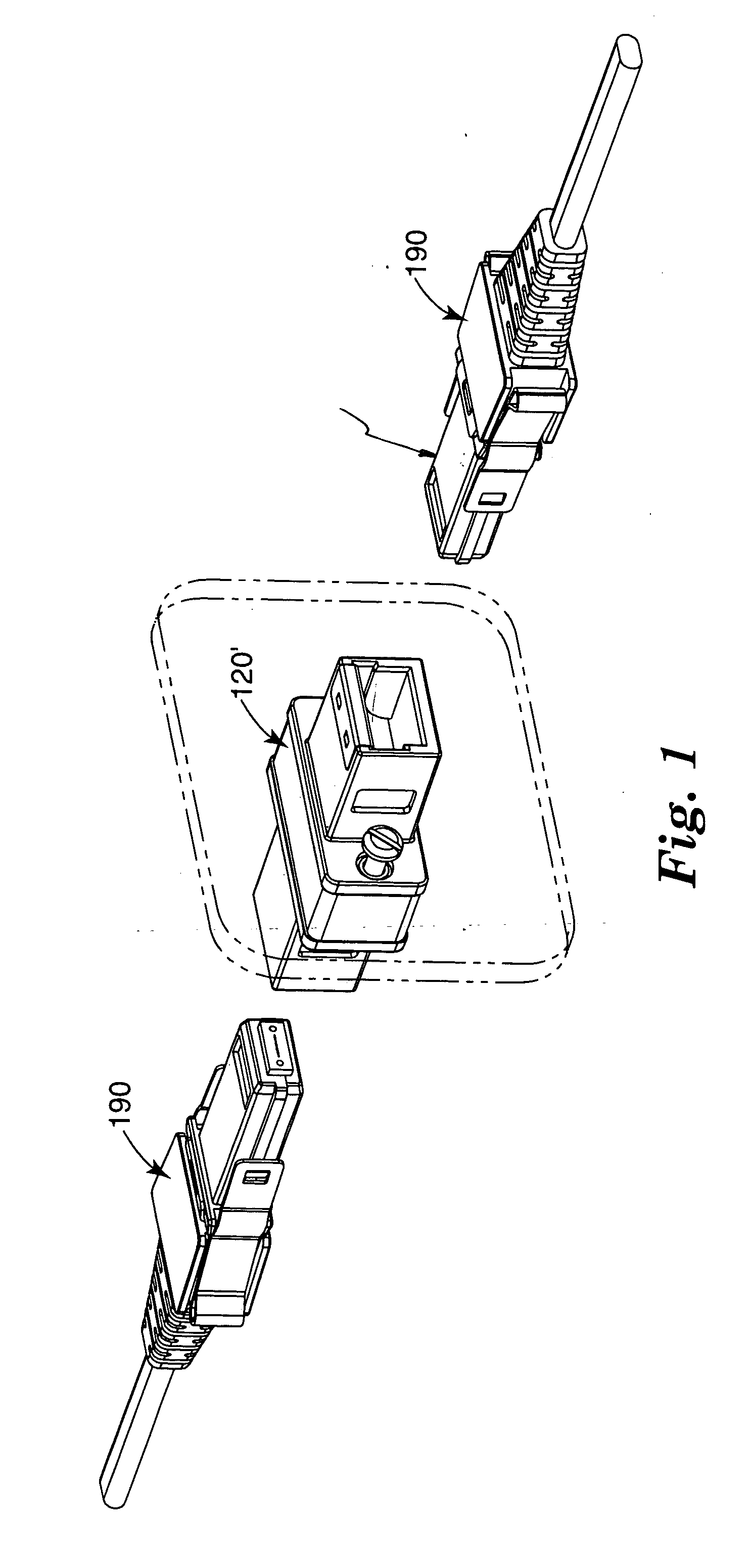
[0042] A bulkhead optical connector system, as illustrated in FIG. 1, having a standard ferrule housing and coupler spacer made of polyetherimide (ULTEM 2300) was provided. The ferrule housing and coupler spacer were formed of a dielectric material and made electrically conductive by depositing on the surface thereof a thin layer of Ni—P alloy layer using a conventional electroless nickel deposition process. The thickness of the Ni—P layer on the ferrule housing and coupler spacer was about 2 microns.

[0043] To measure the effectiveness of the optical connector system in reducing EMI, a microwave transmitter was set up in one room and a microwave receiver was installed in an adjacent room. The connector system under test was mounted in a panel cutout in the wall separating the microwave transmitter and receiver. Preliminary measurements taken ...


PUM


Abstract

A connector system includes an electrically conductive coupling assembly and a first optical connector assembly. The electrically conductive coupling assembly is configured for mounting in a through-opening in a panel. The first optical connector assembly is configured for engagement with the coupling assembly. The first optical connector assembly includes an electrically conductive connector body that is configured to substantially block a first interconnection opening of the coupling assembly when the first optical connector is engaged with the coupling assembly.

Description

BACKGROUND OF THE INVENTION [0001] The present invention generally relates to an interconnect system for use with optical and opto-electronic systems. More particularly, the present invention relates to an optical connector system with electromagnetic interference (EMI) shielding. [0002] In optical and opto-electronic systems, such as telecommunication networks, cabinets are utilized to accommodate optical and opto-electronic devices. Commonly, a plurality of optical, opto-electronic and electrical interconnections are formed at the cabinets. In traditional cabinet designs, the cabinet comprises a box having a front panel (or bulkhead) and a back panel (or backplane). The terms bulkhead and backplane as used in connection with the present invention refer to an interconnection plane where a multiplicity of interconnections may be made, such as with a common bus or other external device. The cabinet may also have a plurality of internal slots (also known as racks), generally parallel ...

Claims


Application Information

Patent Timeline
IPC IPC(8): G02B6/38G02B6/42
CPCG02B6/3821G02B6/3825G02B6/4277G02B6/3885G02B6/3897G02B6/3849G02B6/3893
Inventor COX, LARRY R.LODER, HARRY A.TSAI, CHING-LONGYU, STEVEN Y.
Owner 3M INNOVATIVE PROPERTIES CO
Why Eureka
Try Eureka