
High attenuating earmuff device

a high-attenuation, earmuff technology, applied in the direction of earmuffs, hats, headwear caps, etc., can solve the problems of increasing attenuation, earmuffs not being achieved, annoying or impractical to continue insertion and removal of earplugs,

Inactive Publication Date: 2005-12-29
CABOT SAFETY INTERMEDIATE CORP
View PDF8 Cites 30 Cited by
  • Summary
  • Abstract
  • Description
  • Claims
  • Application Information

AI Technical Summary

Benefits of technology

[0010] An earmuff device is provided, including a connecting band having opposing first and second ends, a pair of earmuff cup assemblies connected to the opposing first and second ends of the connecting band, a first foam disposed at the earmuff cup assemblies, and a second foam disposed at the earmuff cup assemblies, where the first foam comprises a moderately high density foam having highly engineered polymer transition properties with precise loss factor values, modulus values, and polymer transition values and maximum damping at prescribed temperature and frequency conditions, and where the second foam comprises a moderately high density hydrophilic foam particularly employed for optimal property convergence in cell size, air flow, density, and static stiffness. An earmuff cup, an earmuff cushion, and an earmuff liner including the respective first and / or second foams, are also provided.

Problems solved by technology

For example, earmuffs are preferred for intermittent use where continuous insertion and removal of earplugs would be annoying or impractical.
Thus far, however, an earmuff has not been achieved which can provided a suitably high sound attenuation while still providing the comfort and practicability features so desired by the wearer.
While these attempts may have resulted in increases in attenuation, the resulting earmuff is often found to be bulkier, heavier, more difficult to put on, and generally less comfortable than typical earmuff assemblies.

Method used


Image

  • High attenuating earmuff device
  • High attenuating earmuff device
  • High attenuating earmuff device

Examples


Embodiment Construction

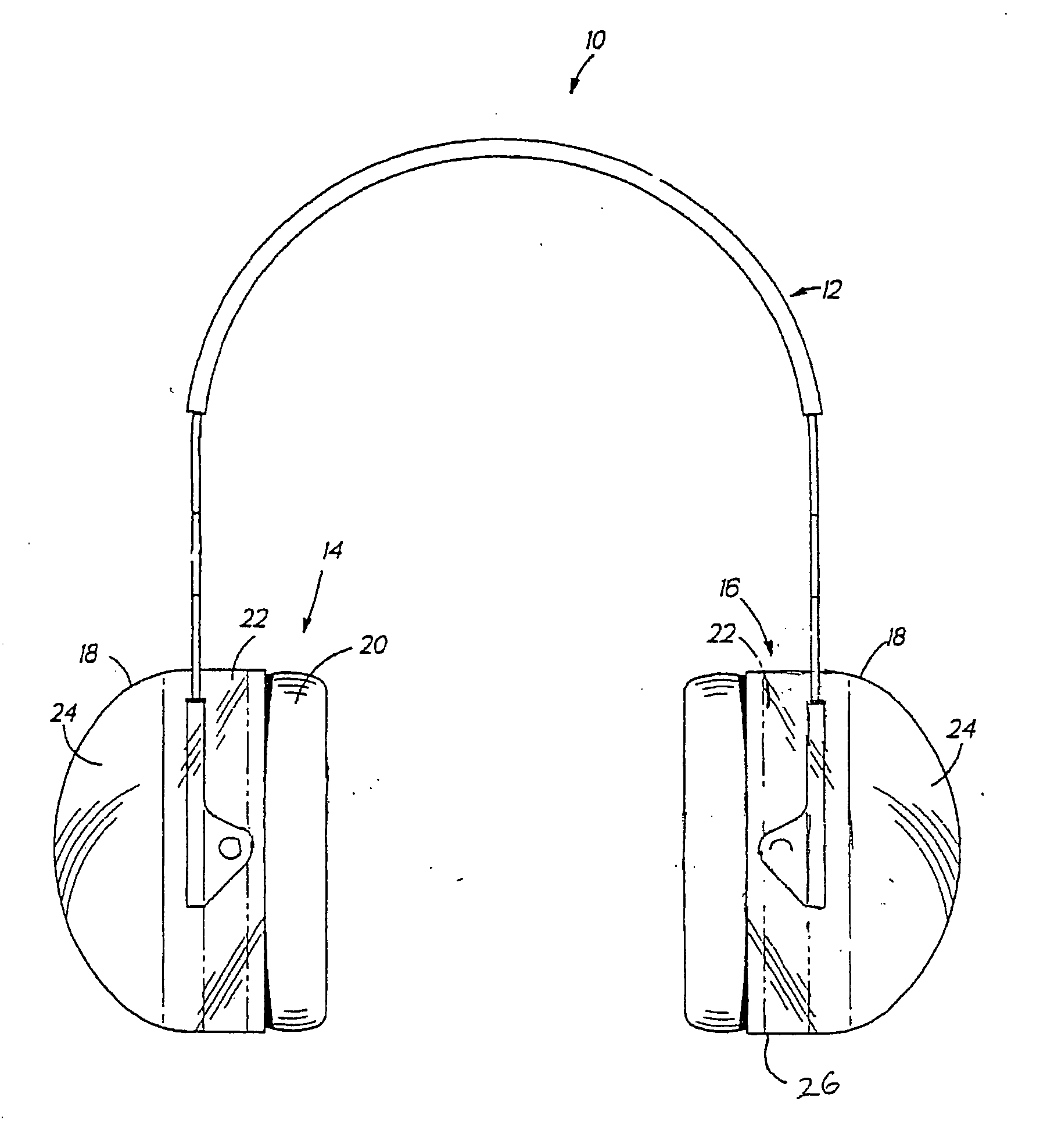
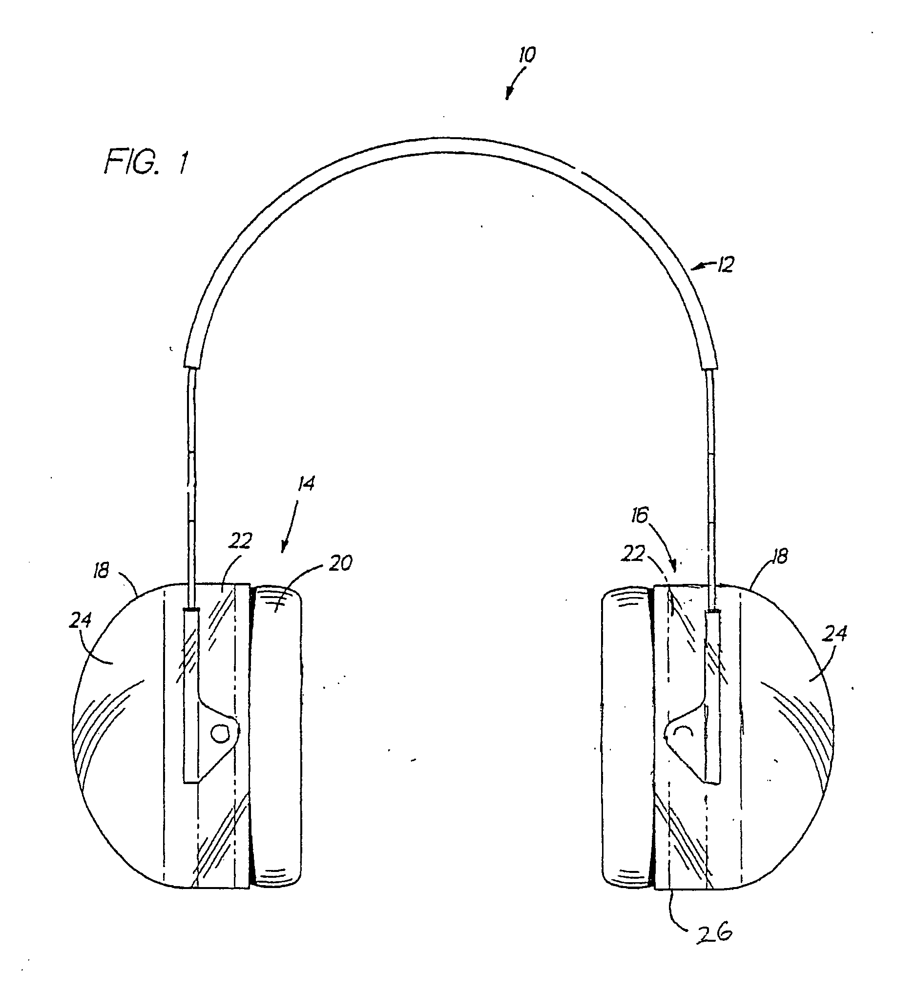
[0015] An earmuff device 10 is shown in FIGS. 1 and 2 in an exemplary embodiment of the invention. The earmuff device 10 broadly comprises a generally U-shaped, resilient connecting band 12 and a pair of earmuff cup assemblies 14 and 16 connected to opposite ends of connecting band 12.

[0016] The ear muff cup assemblies 14 and 16 are affixed to the connecting band 12 in any desired manner. Most preferably, earmuff cup assemblies 14 and 16 may be connected to an adapter which, in turn, is connected to the band 12. The adapter may be configured to allow the ear muff cup assemblies 14 and 16 to pivot or rotate relative the band 12 or, alternatively, the adapter may hold the assemblies 14 and 16 fixedly on the band 12, etc.

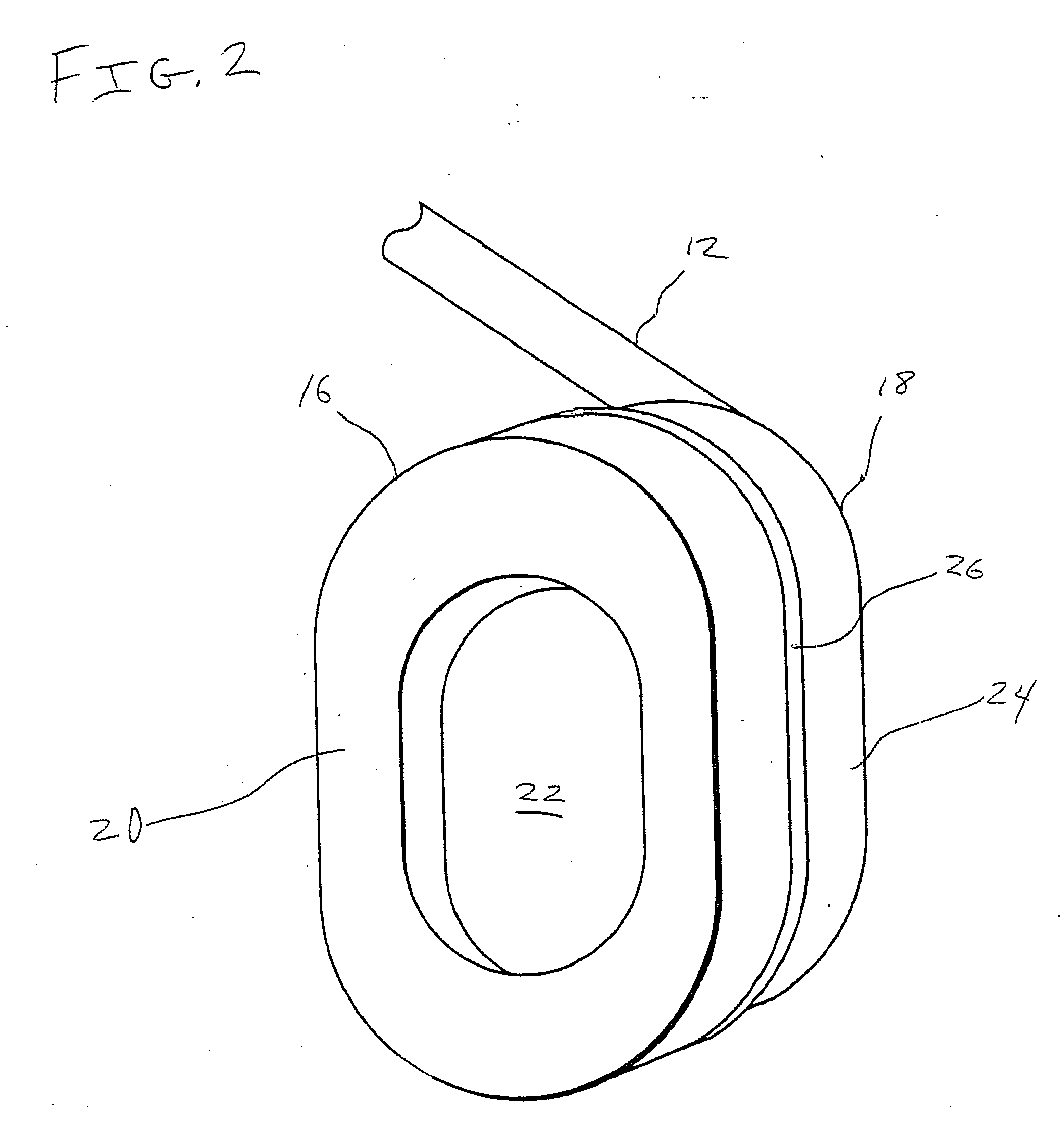
[0017] Each of the earmuff cup assemblies 14 and 16 comprises a rigid earmuff cup 18, a cushion 20, and an earmuff cup liner 22. Rigid cup 18 is generally formed of two pieces, a cup shaped portion 24 and a cushion seal plate 26, which are fixed together at an interf...


PUM


Abstract

An earmuff device is provided, including a connecting band having opposing first and second ends, a pair of earmuff cup assemblies connected to the opposing first and second ends of the connecting band, a first foam disposed at the earmuff cup assemblies, and a second foam disposed at the earmuff cup assemblies, where the first foam comprises a moderately high density foam having highly engineered polymer transition properties with precise loss factor values, modulus values, and polymer transition values and maximum damping at prescribed temperature and frequency conditions, and where the second foam comprises a moderately high density hydrophilic foam particularly employed for optimal property convergence in cell size, air flow, density, and static stiffness. An earmuff cup, an earmuff cushion, and an earmuff liner including the respective first and / or second foams, are also provided.

Description

CROSS-REFERENCE TO RELATED APPLICATION [0001] This application is related to and claims the benefit of U.S. Provisional Patent Application Ser. No. 60 / 538,612 filed on Jan. 23, 2004, which said application is herein incorporated by reference in its entirety.BACKGROUND OF THE INVENTION [0002] 1. Field of the Invention [0003] This invention relates generally to acoustic hearing protective devices and, more particularly, to an earmuff device comprising foam materials for providing a wearer with a high sound attenuation. [0004] 2. Brief Discussion of the Prior Art: [0005] Earmuff devices are commonly used to protect against hearing damage in environments where noise levels are not able to be controlled within safe limits. Such devices generally include a pair of rigid cups connected by a head band, each cup having an interior lined with an acoustical material and a cushion extending from the cup toward the head of a wearer to seal the respective cup to the wearer's head around the ear. ...

Claims


Application Information

Patent Timeline
IPC IPC(8): A42B1/06A61F11/14
CPCA61F11/14
Inventor BERGER, ELLIOTTJAKOBSON, BJORN
Owner CABOT SAFETY INTERMEDIATE CORP
Learn More