Continuous hold-down system

a technology of hold-down system and continuous hold-down, which is applied in the direction of foundation engineering, building types, construction, etc., can solve the problems of isolating each individual level of the building, not being continuous, etc., and achieves the effect of convenient and quick installation

Inactive Publication Date: 2005-12-29
COMMINS ALFRED D
View PDF40 Cites 27 Cited by
  • Summary
  • Abstract
  • Description
  • Claims
  • Application Information

AI Technical Summary

Benefits of technology

[0012] It is an object of the present invention to provide a continuous hold-down system that may be easily and quickly installed.
[0013] It is a further object of the present invention to provide a hold-down system that may be mass produced inexpensively.
[0014] In certain embodiments, the apparatus and method in accordance with the present invention may include a foundation with an anchor, which anchor is composed of threaded rods coupled together and extending through one or more levels of a building or structure. The anchor provides a basis for the individual components of the continuous hold-down system. The take-up units used in the system help maintain tension throughout the system, essentially securing the entire structure to the foundation. Securing the structure to the foundation enables the structure to better withstand various forces acting on the structure. These forces are transferred to the foundation where they can be dissipated more efficiently.
[0015] While previous hold-down systems may be considered useful for similar purposes, the continuous hold-down system described herein is a more effective and efficient system. Previous hold-down systems may not be continuous, thereby isolating each individual level of the building. The continuous nature of the current invention allows the system to compensate for shrinkage or crushing which may occur on any level of the building. Thus, if shrinkage or crushing on one level exceeds the capacity of the system on that level, the system on other levels can compensate for the excess.
[0016] Another feature of this particular continuous hold-down system is that the individual take-up units used in the system are stackable, more than one take-up unit may be stacked providing greater ability to compensate for shrinkage and crushing. This is especially helpful in the continuous system because the system is capable of compensating for shrinkage and crushing which may occur on any level of the building. Therefore, if the top level of the building has a couple of take-up units stacked on top of each other, those units can compensate for any excess shrinkage or crushing throughout the building. This can also be especially helpful on upper levels of a building because shrinkage and crushing that may occur on lower levels tend to be accentuated on upper levels.

Problems solved by technology

Previous hold-down systems may not be continuous, thereby isolating each individual level of the building.

Method used


Image

  • Continuous hold-down system
  • Continuous hold-down system
  • Continuous hold-down system

Examples


Embodiment Construction

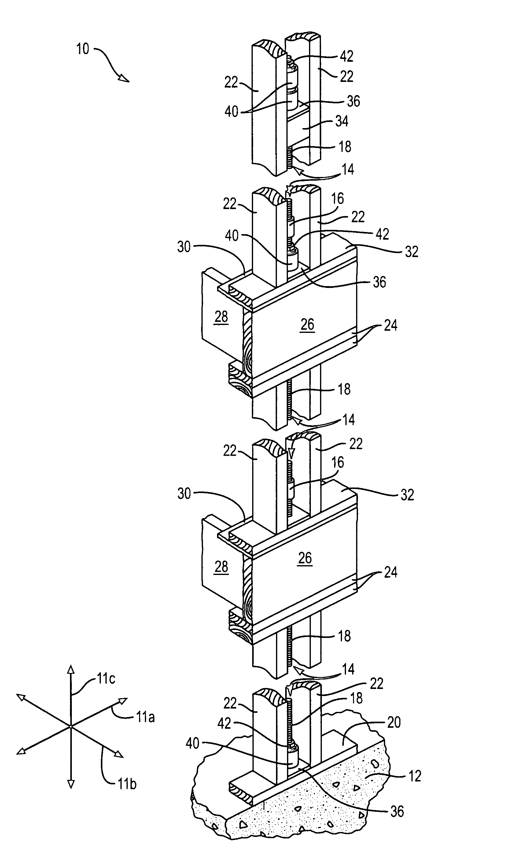
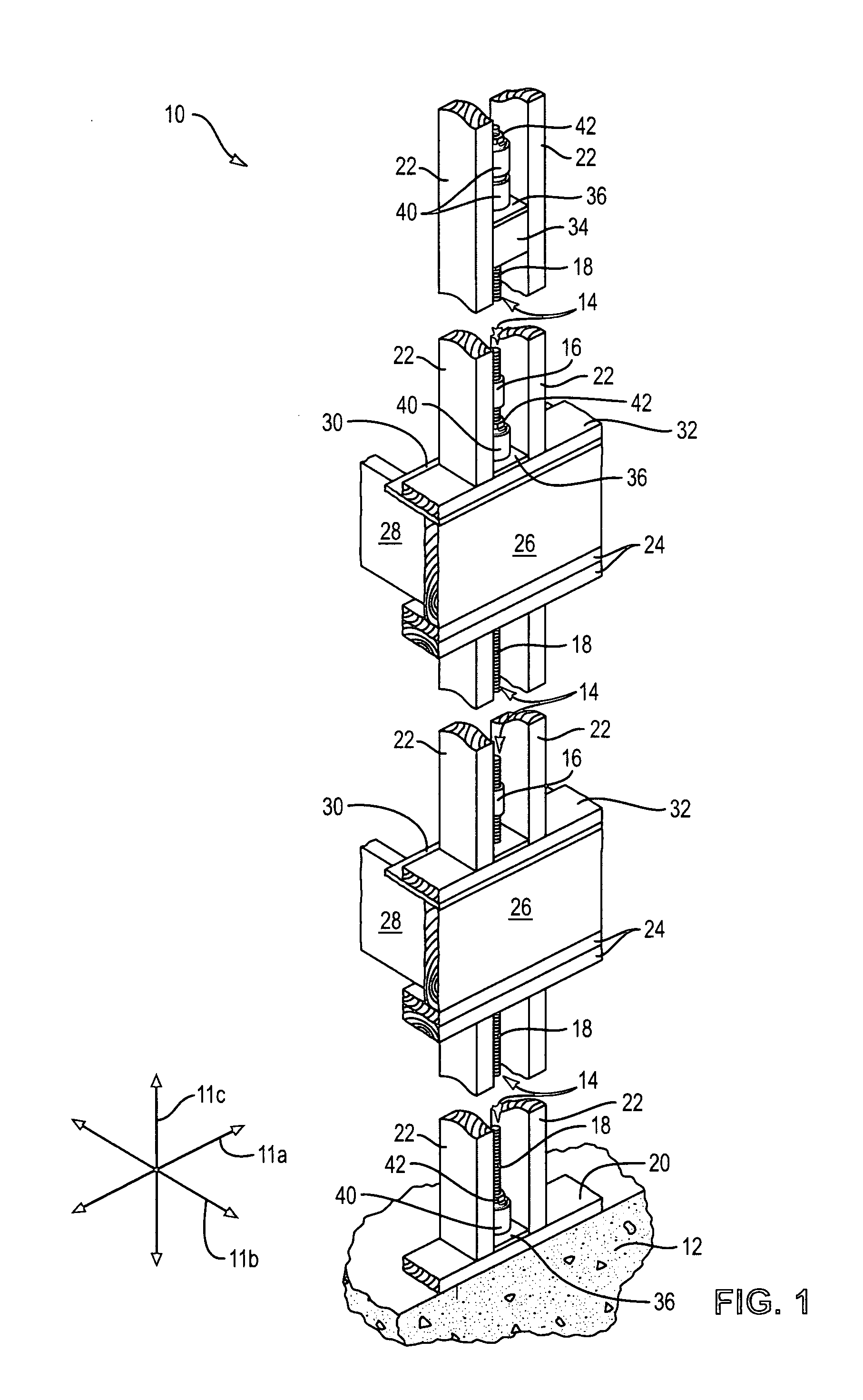
[0032] It will be readily understood that the components of the present invention, as generally described and illustrated in the Figures herein, may be arranged and designed in a wide variety of different configurations. Thus, the following more detailed description of the embodiments of the system and method of the present invention, as represented in FIGS. 1 through 13, is not intended to limit the scope of the invention. The scope of the invention is as broad as claimed herein. The illustrations are merely representative of certain, illustrative embodiments of the invention. Those embodiments of the invention will be best understood by reference to the drawings, wherein like parts are designated by like numerals throughout.

[0033] Several Figures display an automatic take-up unit. This device is described fully in U.S. Pat. No. 6,390,747 issued May 21, 2002, to this inventor, and incorporated herein by reference.

[0034] Those of ordinary skill in the art will, of course, apprecia...


PUM


Abstract

A hold-down system used to secure a building structure to a foundation, thereby enabling the building to better withstand high winds, earthquakes, and the like. The hold-down system is characterized as being continuous and having stackable, individual take-up devices. A continuous hold-down system may include an anchor extending from the foundation through the various stories of the building structure. One or more take-up devices may limit the motion of selected stories with respect to the anchor. Accordingly, the individual take-up devices, acting alone or in a stacked configuration, compensate for settling, wood shrinkage, wood crushing, and the like throughout the entire height of the building structure.

Description

RELATED APPLICATIONS [0001] This application is a continuation of co-pending U.S. patent application Ser. No. 10 / 639,304, filed Aug. 12, 2003 and entitled PORTAL REINFORCEMENT APPARATUS AND METHOD and a continuation-in-part of co-pending U.S. patent application Ser. No. 10 / 602,534, filed Jun. 23, 2003 and entitled SHRINKAGE COMPENSATOR FOR BUILDING TIEDOWNS, which is a continuation of U.S. Pat. No. 6,585,469 issued Jul. 1, 2003 and entitled SHRINKAGE COMPENSATOR FOR BUILDING TIEDOWNS, which is a continuation of U.S. Pat. No. 6,390,747 issued May 21, 2002 and entitled SHRINKAGE COMPENSATOR FOR BUILDING TIEDOWNS.BACKGROUND [0002] 1. Field of the Invention [0003] The present invention relates to building construction, and more specifically, to apparatus for anchoring shear walls to foundations and lower floors. [0004] 2. Background [0005] Strong winds and earthquakes subject walls and others elements of a building to tremendous forces. If these forces are not distributed to the proper ...

Claims


Application Information

Patent Timeline
Patent Type & Authority Applications(United States)
IPC IPC(8): E02D27/00E02D27/32E02D27/42E04B1/00E04B1/26E04B1/35E04H9/14
CPCE04B1/26E04B1/2604E04B2001/268E04H9/14E04B2001/2688E04B2001/2696E04B2001/3583E04B2001/2684
Inventor COMMINS, ALFRED D.
Owner COMMINS ALFRED D
Why Eureka
Try Eureka