Regeneration control method for continuously regenerating diesel particulate filter device

a technology of a filter device and a control method, which is applied in the direction of electrical control, filtration separation, separation processes, etc., can solve the problems of insufficient filter regeneration, filter clogging, filter cannot be regenerated, etc., and achieves efficient regeneration of the filter by removing pm, preventing drivability from deteriorating, and limiting the deterioration in fuel consumption

Inactive Publication Date: 2005-12-29
ISUZU MOTORS LTD
View PDF16 Cites 22 Cited by
  • Summary
  • Abstract
  • Description
  • Claims
  • Application Information

AI Technical Summary

Benefits of technology

[0024] The present invention is devised in order to solve the aforementioned problems. The objective of the present invention is to provide a regeneration control method for the continuously regenerating diesel particulate filter device allowing to regenerate the filter by removing PM efficiently. It limits the deterioration in fuel consumption and at the same time prevents the drivability from deteriorating, by selecting an appropriate control for heating up the exhaust among control for heating up the exhaust gas prepared in a plurality of ways, and by shifting to a regenerating mode operation involving this control for heating up the exhaust gas, in an appropriate period for the regeneration treatment, even if the phase of clogging is on the middle order, through the observation of the state where PM is collected and exhaust temperature or catalyst temperature simultaneously, in a continuously regenerating diesel particulate filter device.

Problems solved by technology

However, in this DPF for collecting PM, clogging progresses along with the collection of PM and the exhaust gas pressure (discharge pressure) along with the increase of the quantity of collected PM, requiring to remove PM from this DPF; hence, several methods and apparatuses are being developed.
Accordingly the filter cannot be regenerated and PM continues to build up in the filter, resulting in filter clogging.
However, in this post-injection, the whole of the injected fuel cannot complete the combustion entirely in a cylinder, but a part thereof is emitted into the exhaust passage as unburned HC or CO.
However in case where it has not become not less than the activation temperature, the unburned HC or CO will be emitted as they are without contributing to heating up the exhaust, thereby causing pollution.
Moreover, the filter regeneration becomes insufficient.
However, since the control for heating up the exhaust gas provided only in this single kind, is composed to securely heat up an exhaust gas of the supposed lowest temperature, this control for heating up the exhaust gas performs the operation for raising temperature, which is far from the operation state of idling operation or low speed operation etc.
Consequently, this control for heating up the exhaust gas for coercively raising the exhaust gas temperature provokes the problem of deteriorated fuel consumption, because heat energy supplied from the fuel or the exterior is consumed unnecessarily for heating up the exhaust gas, or unnecessary equipment is driven.
Further, there is a problem of deterioration of drivability, because engine output variation is provoked by this control for heating up the exhaust, when it is changed over to the regenerating mode operation during the driving.

Method used


Image

  • Regeneration control method for continuously regenerating diesel particulate filter device
  • Regeneration control method for continuously regenerating diesel particulate filter device
  • Regeneration control method for continuously regenerating diesel particulate filter device

Examples


first embodiment

[Regeneration Control Method of the First Embodiment]

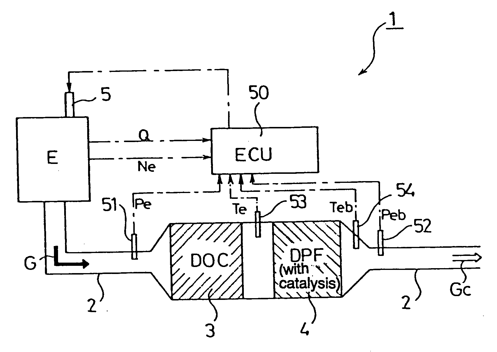
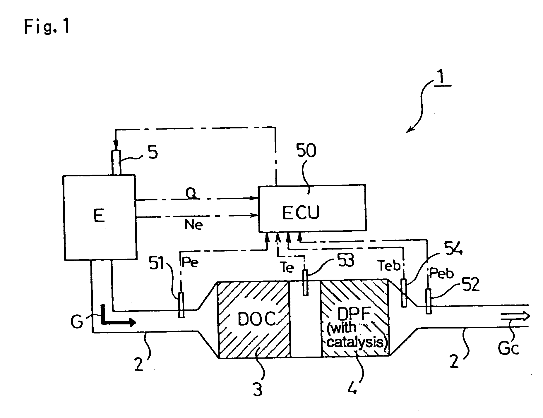
[0080] Next, the regeneration control method of the first embodiment in the continuously regenerating type DPF device 1 of the foregoing composition shall be described.

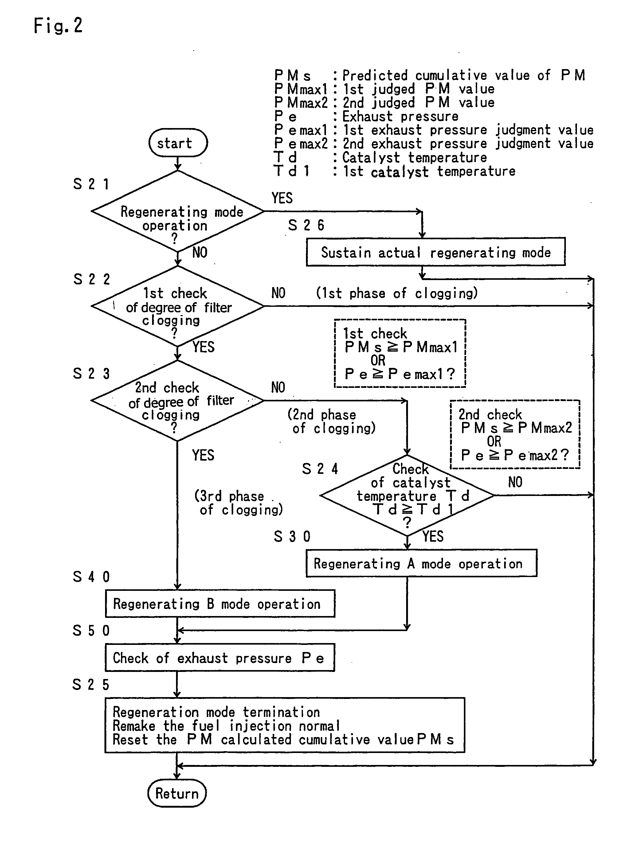
[0081] This regeneration control method is performed following flows as illustrated in FIG. 2 to FIG. 5.

[0082] For the convenience of description, these illustrated flows are shown as a regeneration control flow to be called and executed reiteratively in parallel with the control flow of the engine E. In short, this flow is composed to be called and executed reiteratively every fixed period of time, in parallel during the operation control of the engine E, and not to be called any more, when the control of the engine E terminates, so as to substantially terminate the regeneration control of the filter with catalysis 4, too.

[Outline of Regeneration Control Method]

[0083] In the regeneration control flow of the first embodiment of the present invention, as shown in...

second embodiment

[Regeneration Control Method of the Second Embodiment]

[0121] Now, the regeneration control method of the second embodiment shall be described.

[0122] Though, in the control flow of FIG. 2 to FIG. 5, the judgment of the clogged-filter-state is performed by two checks and the phase of clogging is divided into three phases, similarly, it can be made easily in four or more phases. This control flow in four phases is shown in FIG. 6.

[0123] In the control flow of this FIG. 6, the judgment of filter clogging state is judged by the three checks, in the first phase of clogging, the regeneration is determined unnecessarily, in the second phase of clogging, the regenerating A mode operation is performed only when the catalyst temperature Td is not less than the catalyst active temperature Td1, while in the third phase of clogging, the regenerating B mode operation involving the control for heating up the exhaust gas is performed only when the engine operation state (Q, Ne) is in a specified r...


PUM

PropertyMeasurementUnit
temperatureaaaaaaaaaa

Abstract

A regeneration control method for regenerating a continuously regenerating diesel particulate filter device capable of regenerating a filter by efficiently removing PM while suppressing the deterioration of fuel consumption and preventing a drivability from being deteriorated, wherein the clogged-state of the filter is judged in three or more phases of the clogged-state and, when the clogged-state of the filter reaches a specified phase, a specified regenerating mode operation set in correspondence with the reached phase is performed.

Description

CROSS-REFERENCE TO RELATED APPLICATIONS [0001] This application is a divisional application of U.S. patent application Ser. No. 10 / 416,714 filed on May 14, 2003, now pending, the contents of which are incorporated by reference, which is based on PCT Application PCT / JP02 / 06375 filed Jun. 26, 2002, which claims priority to Japanese Application JP2001-192387 filed Jun. 26, 2001.BACKGROUND OF THE INVENTION [0002] 1. Field of the Invention [0003] The present invention concerns a regeneration control method for continuously regenerating a diesel particulate filter device provided with a filter, which purifies the exhaust gas by collecting particulate matter of the diesel engine. [0004] 2. Description of the Related Art [0005] The exhaust gas quantity of particulate matter (PM: particulate matter: referred to as PM hereinafter) exhausted from the diesel engine is regulated strictly year by year with NOx, CO, HC and so on. Technologies for reducing the quantity of PM discharged outside, by ...

Claims


Application Information

Patent Timeline
Patent Type & Authority Applications(United States)
IPC IPC(8): B01D39/14B01D46/42F02D43/00B01D53/86B01D53/94F01N3/02F01N3/023F01N3/025F01N3/029F01N3/035F01N13/02F02D41/02F02D41/04F02D41/40
CPCF01N3/023F01N3/0231F01N3/035F01N2430/08F01N2430/085F02D41/029F01N13/009F02D41/405F02D2200/0802F02D2200/0812Y02T10/44F01N13/0097F02D41/1448Y02T10/40
Inventor IMAI, TAKEHITOSUZUKI, TSUNEOGABE, MASASHIOCHI, NAOFUMI
Owner ISUZU MOTORS LTD
Why Eureka
Try Eureka