High admittance acoustic liner

a high-admission, acoustic liner technology, applied in the field of acoustic liner, can solve the problems of reducing the acoustic admittance of the resonator, degrading the acoustic admittance, and attenuating noise, so as to improve the acoustic admittance, and the effect of high-admission

Active Publication Date: 2005-12-29
RAYTHEON TECH CORP
View PDF26 Cites 60 Cited by
  • Summary
  • Abstract
  • Description
  • Claims
  • Application Information

AI Technical Summary

Benefits of technology

[0011] It is another object to provide an acoustic liner whose high admittance helps compensate for the difficulty of attenuating low frequency noise in applications where severe constraints are imposed on the volume of the Helmholtz resonator chamber.
[0012] According to one embodiment of the invention, an acoustic liner includes a resonator chamber and a face sheet. A coolant plenum resides between the face sheet and the chamber. Coolant bypasses the reso...

Problems solved by technology

During operation, the array of resonators attenuates noise attributable to pressure disturbances in the fluid stream.
Despite the many merits of Helmholtz resonator acoustic liners, various factors can degrade their acoustic admittance.
For example, when the liner is used to line a fluid handling duct, the flowing fluid grazes past the inlets to the resonator necks and, in doing so, reduces the acoustic admittance of the resonators.
This occurs because the grazing fluid produces a region of fluid recirculation inside the neck, which reduces the effective area of the neck, thereby decreasing the acoustic admittance.
The loss of acoustic admittance becomes more severe with increasing coolant Mach number.
Sp...

Method used


Image

  • High admittance acoustic liner
  • High admittance acoustic liner
  • High admittance acoustic liner

Examples


Embodiment Construction

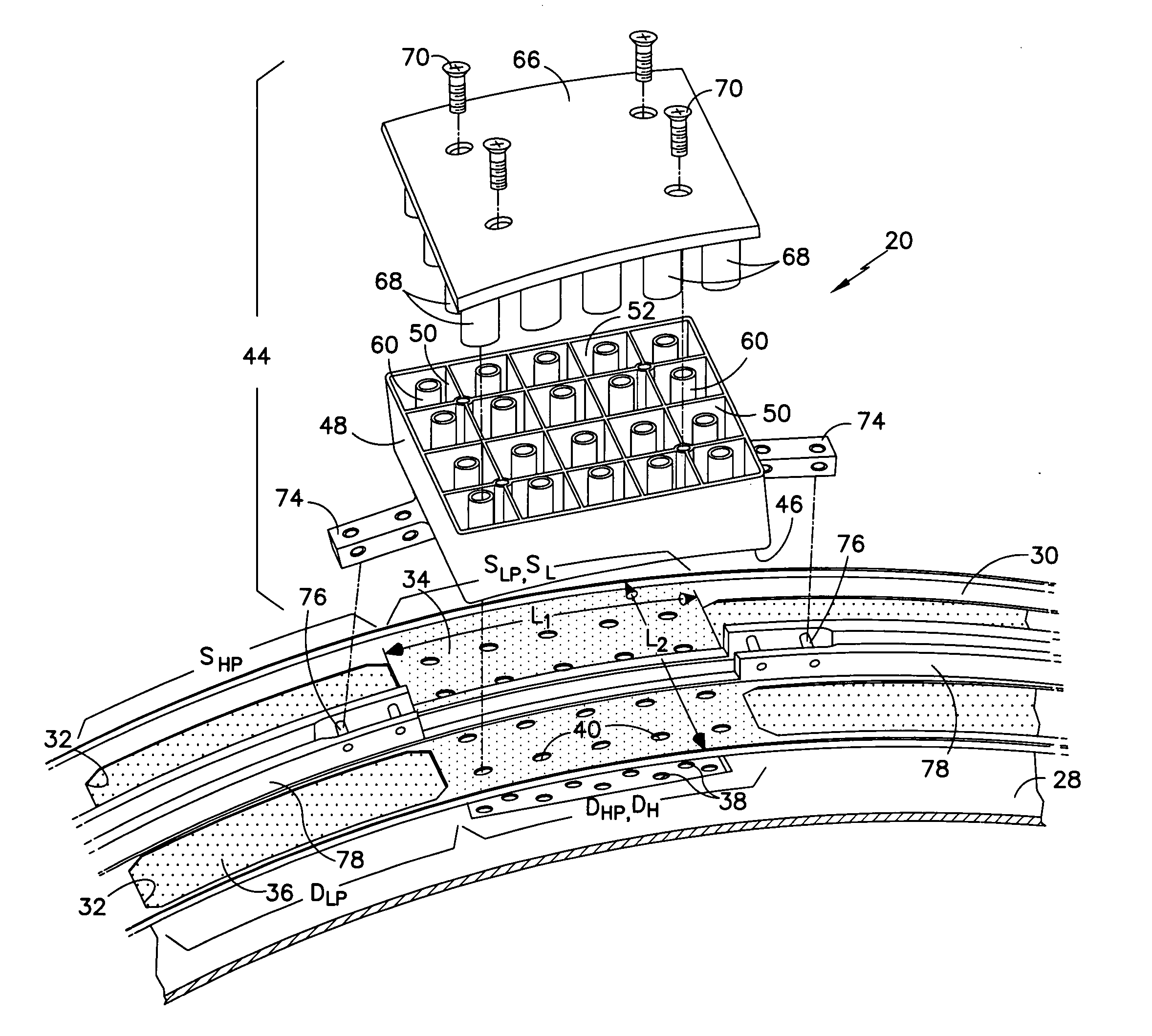
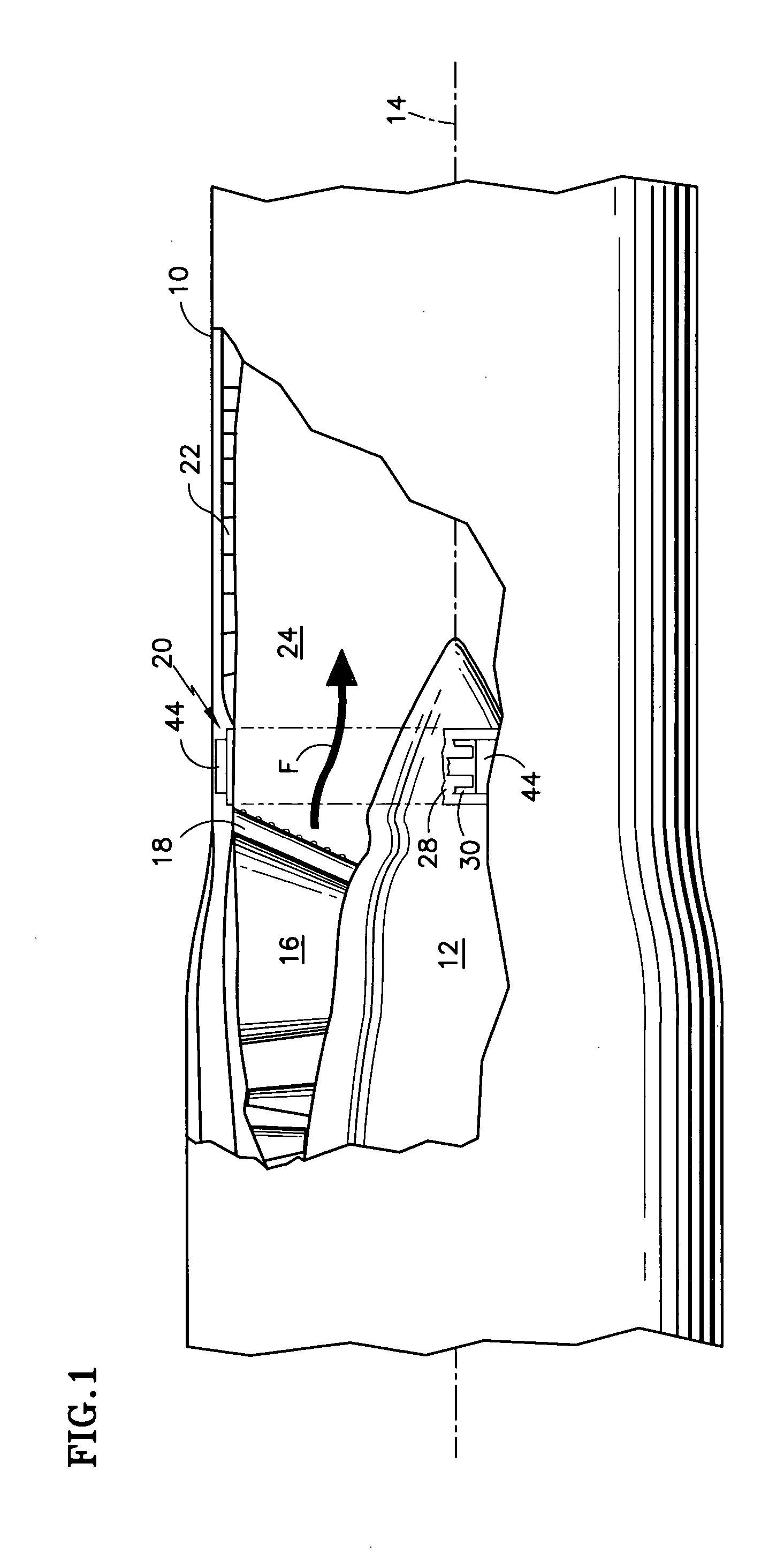
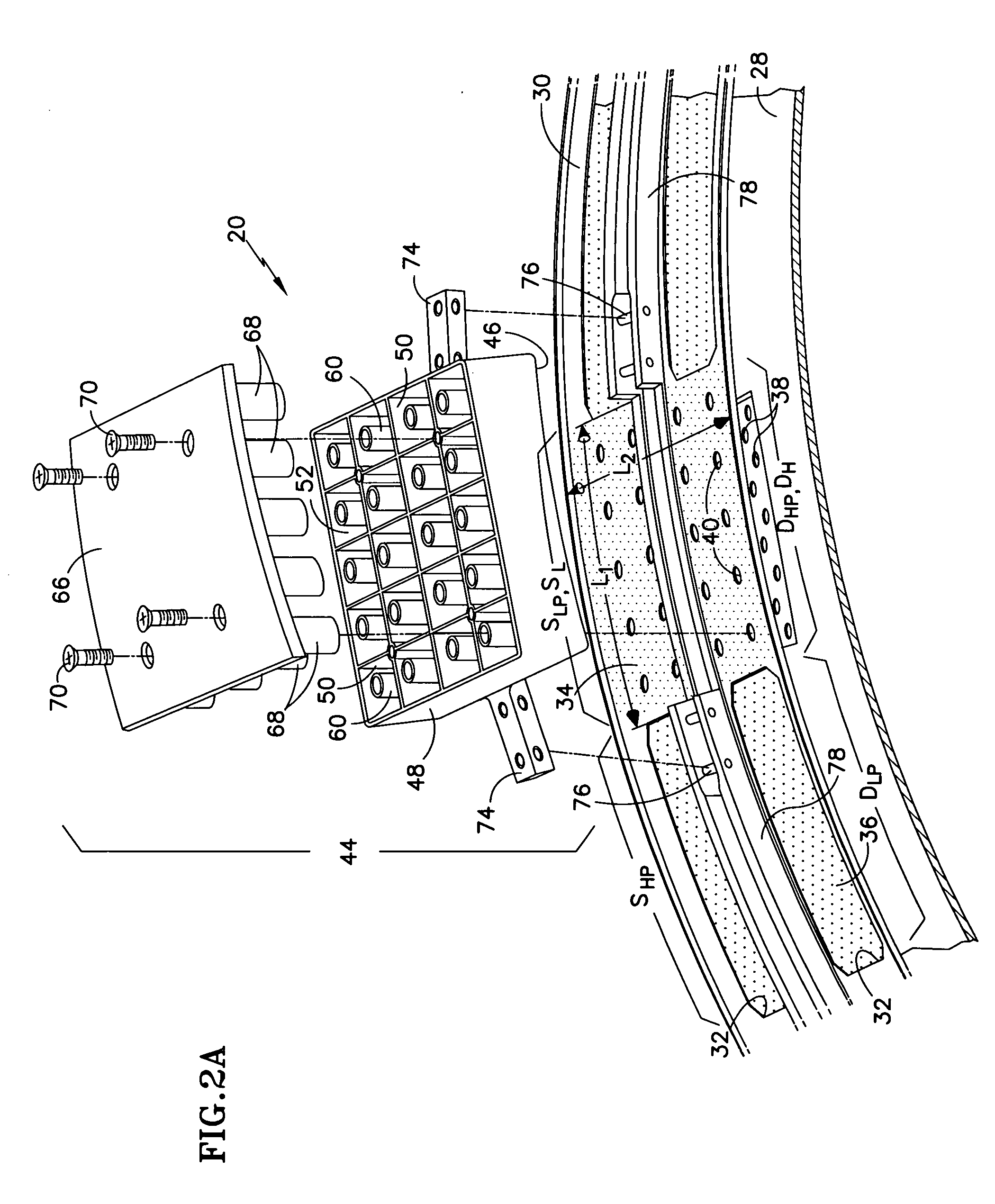
[0026] Referring to FIGS. 1 and 2A, an afterburning, variable cycle gas turbine engine for a high performance aircraft includes an outer case 10 and an internal centerbody 12 circumscribing an engine axis 14. The engine internal components also include an array of circumferentially distributed turbine exhaust vanes 16, an afterburner flameholder 18 integral with each vane 16, a modulated engine cooling (MEC) module 20, and an afterburner duct 22. A working medium flowpath 24 extends axially along the length of the engine. During engine operation, a fluid stream F comprising hot combustion gases flows through the vane array 16, the MEC module 20, and the afterburner duct 22. When the aircraft pilot selects afterburning operation, the engine fuel system introduces fuel into the combustion gases in the vicinity of the flameholder. The combustion gases ignite the fuel to produce additional thrust.

[0027] A pre-existing MEC module 20 includes an MEC duct 28 and an MEC strap 30 encircling...


PUM


Abstract

A cooled acoustic liner useful in a fluid handling duct includes a resonator chamber 52 with a neck 56, a face sheet 86, and a coolant plenum 80 residing between the face sheet and the chamber. Coolant bypasses the resonator chamber, rather than flowing through it, resulting in better acoustic admittance than in liners in which coolant flows through the resonator chamber and neck. In one embodiment, the liner also includes a graze shield 88. Openings 40, 38 penetrate both the face sheet and the shield to establish a relatively low face sheet porosity and a relatively high shield porosity. The shielded embodiment of the invention helps prevent a loss of acoustic admittance due to fluid grazing past the liner. Another embodiment that is not necessarily cooled, includes the resonator chamber, low porosity face sheet and high porosity shield, but no coolant plenum for bypassing coolant around the resonator chamber. An associated method of retrofitting an acoustic treatment into a fluid handling module includes installing openings in the module and mounting a resonator box 44 on the module so that the inlets to the resonator necks register with the installed openings.

Description

STATEMENT OF GOVERNMENT INTEREST [0001] This invention was made under U.S. Government Contract F33657-99-D-2051-0008. The Government has certain rights in the invention.TECHNICAL FIELD [0002] This invention relates to acoustic liners and particularly to a liner having a high acoustic admittance for achieving superior noise attenuation. BACKGROUND OF THE INVENTION [0003] Acoustic liners are used in fluid handling ducts to attenuate undesirable noise associated with a stream of fluid flowing through the duct. Examples of such ducts include the inlet and exhaust system ducts of gas turbine engines. A typical acoustic liner includes a back sheet, a face sheet spaced from the back sheet, and a series of walls that extend between the face sheet and back sheet to define an array of chambers. A set of holes or necks, usually one per chamber, penetrates the face sheet to establish communication between the chamber and the fluid stream. Each chamber and its associated neck is a Helmholtz reso...

Claims


Application Information

Patent Timeline
IPC IPC(8): B64D33/02B64F1/26E04H17/00F02C7/045F02C7/24F02K1/82F02K99/00G10K11/00G10K11/172
CPCB64D2033/0206F02C7/045F02C7/24F05D2260/96G10K11/172Y02T50/671F02K1/827Y02T50/60
Inventor PROSCIA, WILLIAMJONES, CHRISTOPHER D.PATRICK, WILLIAM P.
Owner RAYTHEON TECH CORP
Why Eureka
Try Eureka