Method of manufacturing a tank of thermoplastic material including a portion in relief for mounting an attachment, and a tank manufactured thereby

Inactive Publication Date: 2005-12-29
INERGY AUTOMOTIVE SYST RES (SA)
View PDF43 Cites 23 Cited by
  • Summary
  • Abstract
  • Description
  • Claims
  • Application Information

AI Technical Summary

Benefits of technology

[0018] The invention makes it possible to provide a shape for mounting an attachment inside the tank without any need to cut through or pierce the wall of the tank, and this is particularly advantageous when the wall in question includes one or more layer(s) forming a barrier against hydrocarbons.
[0019] Means for mounting an attachment inside the tank are thus obtained in simple and reliable manner without the presence of such

Problems solved by technology

The attachment then projects into the inside of the attachment, thereby reducing the height available for performing the function for which the attachment,

Method used


Image

  • Method of manufacturing a tank of thermoplastic material including a portion in relief for mounting an attachment, and a tank manufactured thereby
  • Method of manufacturing a tank of thermoplastic material including a portion in relief for mounting an attachment, and a tank manufactured thereby
  • Method of manufacturing a tank of thermoplastic material including a portion in relief for mounting an attachment, and a tank manufactured thereby

Examples


Example

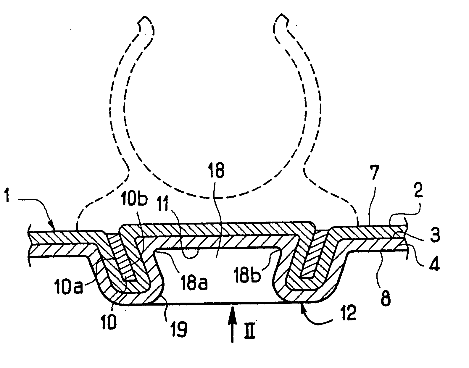
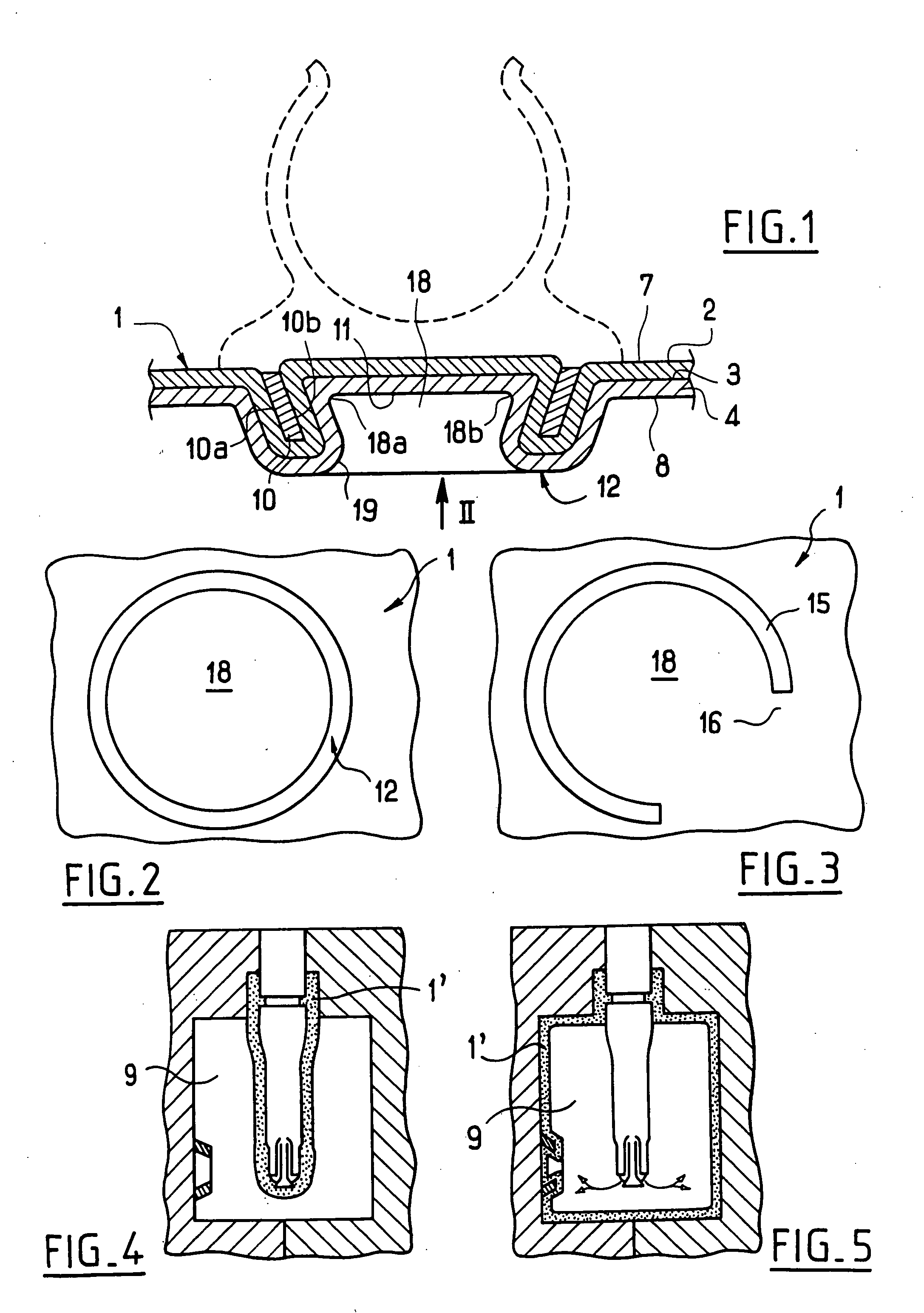
[0069]FIG. 1 shows a portion of the wall 1 of the body of a motor vehicle fuel tank.

[0070] This wall 1 has a multi-layer structure, comprising in succession: an outer layer 2 which defines practically the entire outside face 7 of the tank (and made of polyethylene in this example); an intermediate layer 3 forming a barrier against hydrocarbons (and made of EVOH in this example; and an inner layer 4 defining the inside face 8 of the tank (and made of polyethylene in this example).

[0071] In the embodiment described, the multi-layer structure includes a layer of adhesive between each inner or outer layer 4 or 2 and the intermediate layer 3 in order to improve the cohesion of the tank as a whole.

[0072] In this embodiment, an annularly shaped insert 10 is integrated in the wall 1 of the tank.

[0073] The insert 10 it used for providing mounting means 12 defining a housing 18 inside the tank and having an opening 19 of smaller diameter than its end wall 11.

[0074] The housing 18 is desi...


PUM

PropertyMeasurementUnit
Heataaaaaaaaaa
Thermoplasticityaaaaaaaaaa

Abstract

A method provides a tank out of blown, thermoformed, or rotomolded thermoplastic material with a portion in relief for enabling mounting of an attachment inside the tank. The method includes making the portion in relief on the inside of the tank, the portion in relief enabling an attachment to be mounted inside the tank. The portion in relief is made by mounting a mounting member on the wall of the tank. Preferred mounting is by heat-sealing. The wall of the tank includes at least a layer of thermoplastic material and preferably includes a layer that forms a barrier against hydrocarbons. A tank with a portion in relief mounted on an inside wall is also provided.

Description

INCORPORATION BY REFERENCE [0001] This is a division of application Ser. No. 09 / 824,051 filed Apr. 3, 2001, the disclosure of which is hereby incorporated herein by reference in its entirety.BACKGROUND [0002] The present invention relates to a method of making a tank of blown, thermoformed, or rotomolded thermoplastic material. More particularly, but not exclusively, the invention relates to making a fuel tank for a motor vehicle. [0003] A fuel tank must be designed to prevent fuel being lost through its wall, in particular by diffusing through the thermoplastic material. [0004] To do this, it is known that the tank can be made from a multi-layer parison that includes a barrier-forming layer constituted by a material having good impermeability to hydrocarbons both in gaseous and in liquid form. [0005] By way example, such a layer can be based on EVOH. [0006] In general, a tank made in this way gives satisfaction concerning hydrocarbon emissions. [0007] It is also necessary to be abl...

Claims


Application Information

Patent Timeline
IPC IPC(8): B29C41/04B29C41/20B29C49/06B29C49/20B29C51/12B29C65/02B29C65/56B29C65/58
CPCB29C41/04Y10T29/49876B29C49/06B29C49/20B29C51/12B29C65/02B29C65/56B29C65/58B29C2049/2017B29L2031/7172B60K2015/03453B29C66/53245B29C66/474Y10T29/4987B29C41/20B29C66/71B29C66/61B29C66/112B29C66/1122B29C66/114B29C66/7234B29C66/12441B29C2949/0715B29K2023/086B29K2023/065B29K2023/00
Inventor GOMBERT, PATRICEROSSEEL, ALEXIS
Owner INERGY AUTOMOTIVE SYST RES (SA)
Why Eureka
Try Eureka