Method of molding progressive cavity pump stators

a technology of progressive cavity and stators, which is applied in the direction of machines/engines, manufacturing tools, liquid fuel engines, etc., can solve the problems of rotors flexing and bending during operation, early delamination or other damage to stators, and difficult in practice to uniformly form elastomeric stators

Inactive Publication Date: 2005-12-29
BAKER HUGHES INC
View PDF8 Cites 12 Cited by
  • Summary
  • Abstract
  • Description
  • Claims
  • Application Information

AI Technical Summary

Benefits of technology

[0010] The invention provides devices and methods for construction of a stator for a progressive cavity pump. The invent

Problems solved by technology

Additionally, unevenness in the thickness of the stator wall can cause the rotor to flex and bend during operation.
This unevenness may also create uneven stresses in the elastomer during operation, resulting in early delamination or other damage to the stator.
Even and uniform formation of the elastomeric stator is often difficult in practice since the stator housing is axially quite long.
During molding of the stator lining, several factors work against achieving a uniform stator.
However, this can be cumbersome in practice due to the very long length of the stator tube.
During molding, the raw injected elastomer is very viscous and, as it flows into the mold to fill the mold space, i

Method used


Image

  • Method of molding progressive cavity pump stators
  • Method of molding progressive cavity pump stators
  • Method of molding progressive cavity pump stators

Examples


Embodiment Construction

[0021] The term “progressive cavity pump,” as used in the specification and claims herein, is meant to refer to an entire class of devices, including mud motors, and Moineau fluid pumps that utilize elastomer-lined helical stators and rotatable rotors.

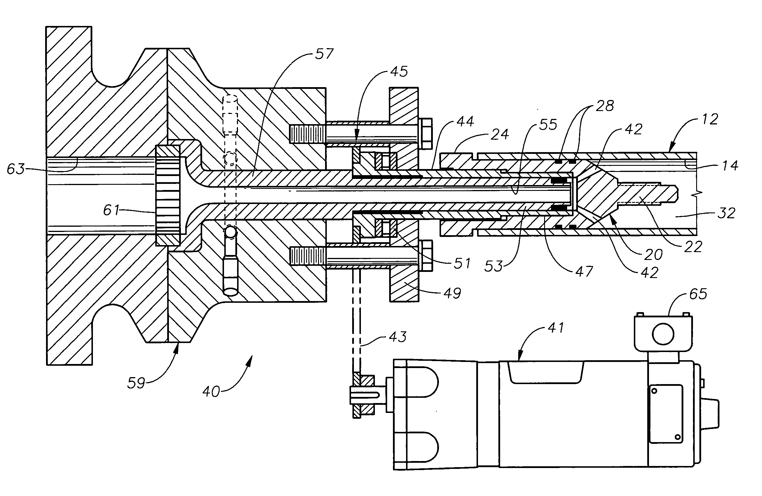
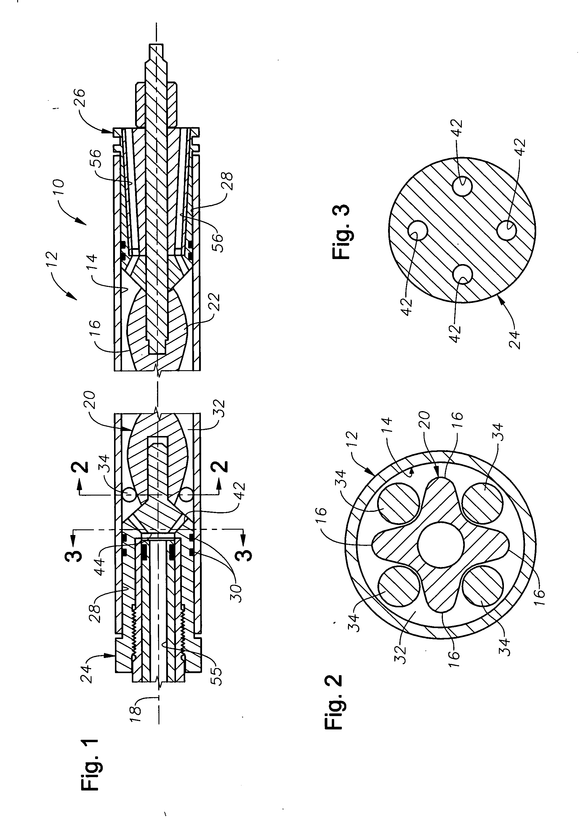
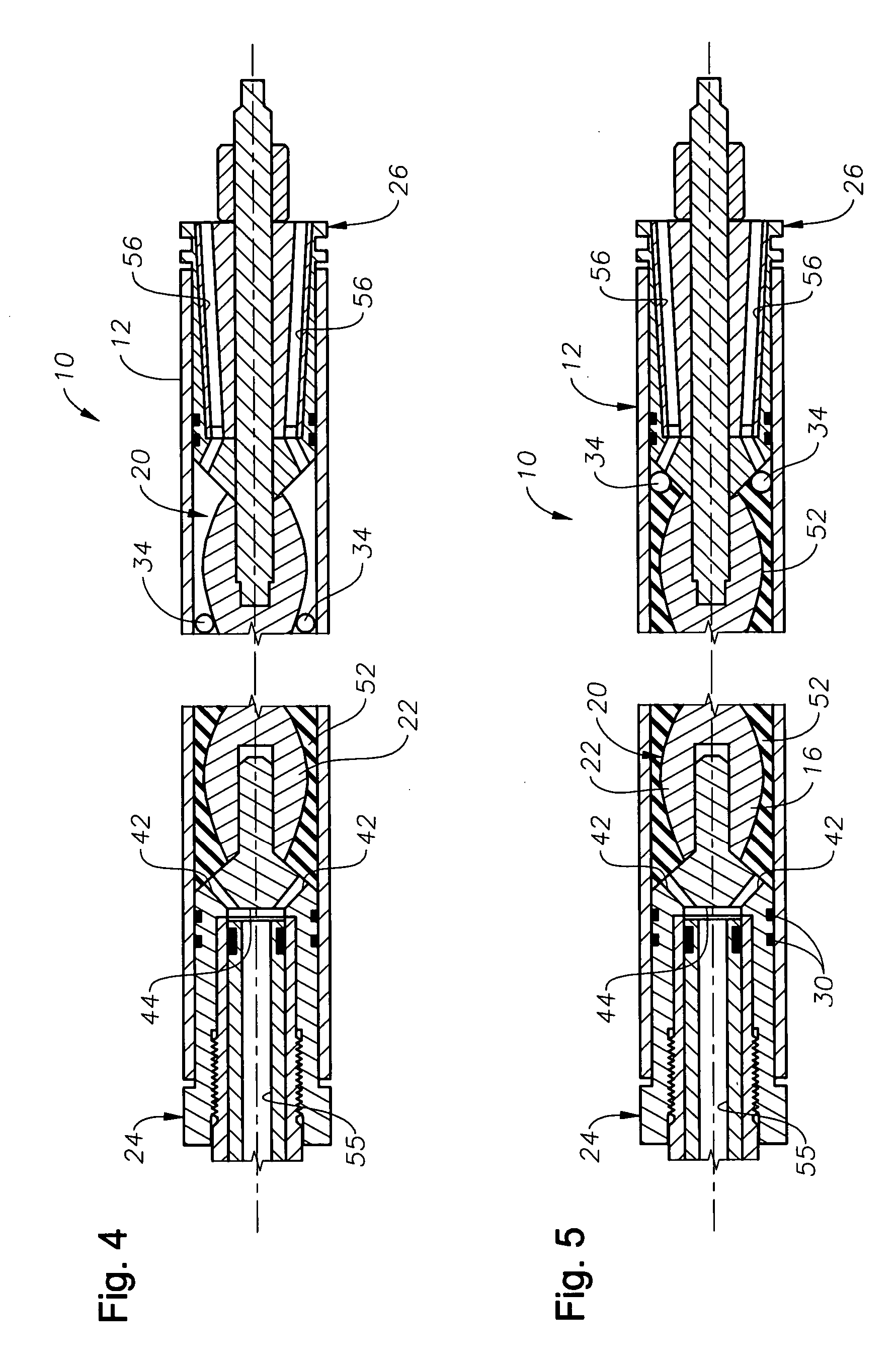
[0022]FIGS. 1-5 illustrate an exemplary mold assembly 10 that is constructed in accordance with the present invention and used for construction of a stator for a progressive cavity pump or motor. The mold assembly 10 includes a tubular metal stator housing 12 that defines an interior bore 14. It is noted that, in practice, the stator housing 12 may be 30 feet or more in length. The housing 12 has a central longitudinal axis, depicted at 18.

[0023] A core assembly 20 is removably disposed within the stator housing 12 during the molding and curing process. The core assembly 20 includes a central, reduced diameter portion 22 with an enlarged diameter portion 24, 26 at each axial end. One or both of the enlarged diameter portions 24, 26 a...


PUM

PropertyMeasurementUnit
Angular velocityaaaaaaaaaa

Abstract

Devices and methods for construction of a stator for a progressive cavity pump without the off centering effect created by gravity. A stator mold is assembled by placing a center section, or core, inside an outer stator housing tube to form a mold assembly. The core has a narrow central portion and a cone-shaped end portion at each axial end. The end assemblies provide an interference fit within the outer housing tube and retain the narrow central portion centrally within the housing tube. A mold space, or injection space, is defined between the housing tube and the core. Traveling spacers are disposed within the mold injection space and are capable of lateral movement therewithin. During injection molding and curing, the mold assembly is oriented in a substantially horizontal position and rotated about its central longitudinal axis.

Description

BACKGROUND OF THE INVENTION [0001] 1. Field of the Invention [0002] The invention relates generally to the design and construction of progressive cavity pumps. [0003] 2. Description of the Related Art [0004] Progressive cavity pumps incorporate a rotor that rotates inside of a stator assembly. These types of pumps are also sometimes referred to as Moineau pumps. The stator assembly has an outer tubular stator housing and an elastomeric lining that is shaped with a number of spiral lobes. The rotor has a helical shape that engages the stator. [0005] In constructing a progressive cavity pump, it is important to form the elastomeric lining as evenly and uniformly as possible. During operation of the pump, the elastomer gets hot. Hot spots can develop where there is a weakness in the elastomeric stator wall. Additionally, unevenness in the thickness of the stator wall can cause the rotor to flex and bend during operation. This unevenness may also create uneven stresses in the elastomer ...

Claims


Application Information

Patent Timeline
IPC IPC(8): B29C33/00B29C45/56F04C2/107
CPCB29C45/5605F04C2230/21F04C2/1075B29L2031/7496
Inventor NEUROTH, DAVID H.
Owner BAKER HUGHES INC
Why Eureka
Try Eureka