Method and apparatus for applying liquid compositions in rail systems

a liquid composition and rail system technology, applied in the direction of rail lubrication, railway auxiliary equipment, locomotives, etc., can solve the problems of high noise level, inability to move between the wheel and the rail, and large wear of mechanical components such as wheels, rails and other rail components, so as to increase the capacity of the reserv

Active Publication Date: 2005-12-29
KELSAN TECH
View PDF9 Cites 14 Cited by
  • Summary
  • Abstract
  • Description
  • Claims
  • Application Information

AI Technical Summary

Benefits of technology

[0041] An advantage of placing the liquid composition application system in a rail car is that the reservoir capacity may be increased from that available in a locomotive, yet space in the rail car is impacted to minimal degree and the carrying capacity of the rail car may still carry an appreciable revenue generating load. Furthermore, by having the application system located in a rail car, locomotives may be added, removed, or their relative position with respect to each other changed without the need to consider the location of the application of the liquid composition to the rail as in most cases it will be behind all of the drive wheels of the locomotive. In the case of a distributed power, when an additional locomot

Problems solved by technology

For example, many steel-rail and steel-wheel transportation systems including freight, passenger and mass transit systems suffer from the emission of high noise levels and extensive wear of mechanical components such as wheels, rails and other rail components.
However, because the wheel and the rail are profiled, often misaligned and subject to motions other than strict rolling, the respective velocities at which the wheel and the rail move through the zone of contact are not always the same on a tangent section of the railway, causing sliding movement between the wheel and the rail.
This is not possible on fixed-axle railcars.
Sliding movement may also arise when traction is lost on inclines thereby causing the driving wheels to slip.
In addition, when the when railcars pass through a curvature, the centripetal force will cause additional friction between the flanges of the profiled railcar wheel and the inside side of the ‘high rail’ of the curvature.
At creepage levels larger than about 1%, appreciable frictional forces are generated due to sliding, and these frictional forces result in noise and wear of components (H. Harrison, T. McCanney and J. Cotter (2000), Recent Developments in COF Measurements at the Rail/Wheel Interface, Proceedings The 5th International Conference on C

Method used


Image

  • Method and apparatus for applying liquid compositions in rail systems
  • Method and apparatus for applying liquid compositions in rail systems
  • Method and apparatus for applying liquid compositions in rail systems

Examples


Embodiment Construction

[0058] The present invention relates to liquid composition application systems used in rail systems.

[0059] The following description is of a preferred embodiment.

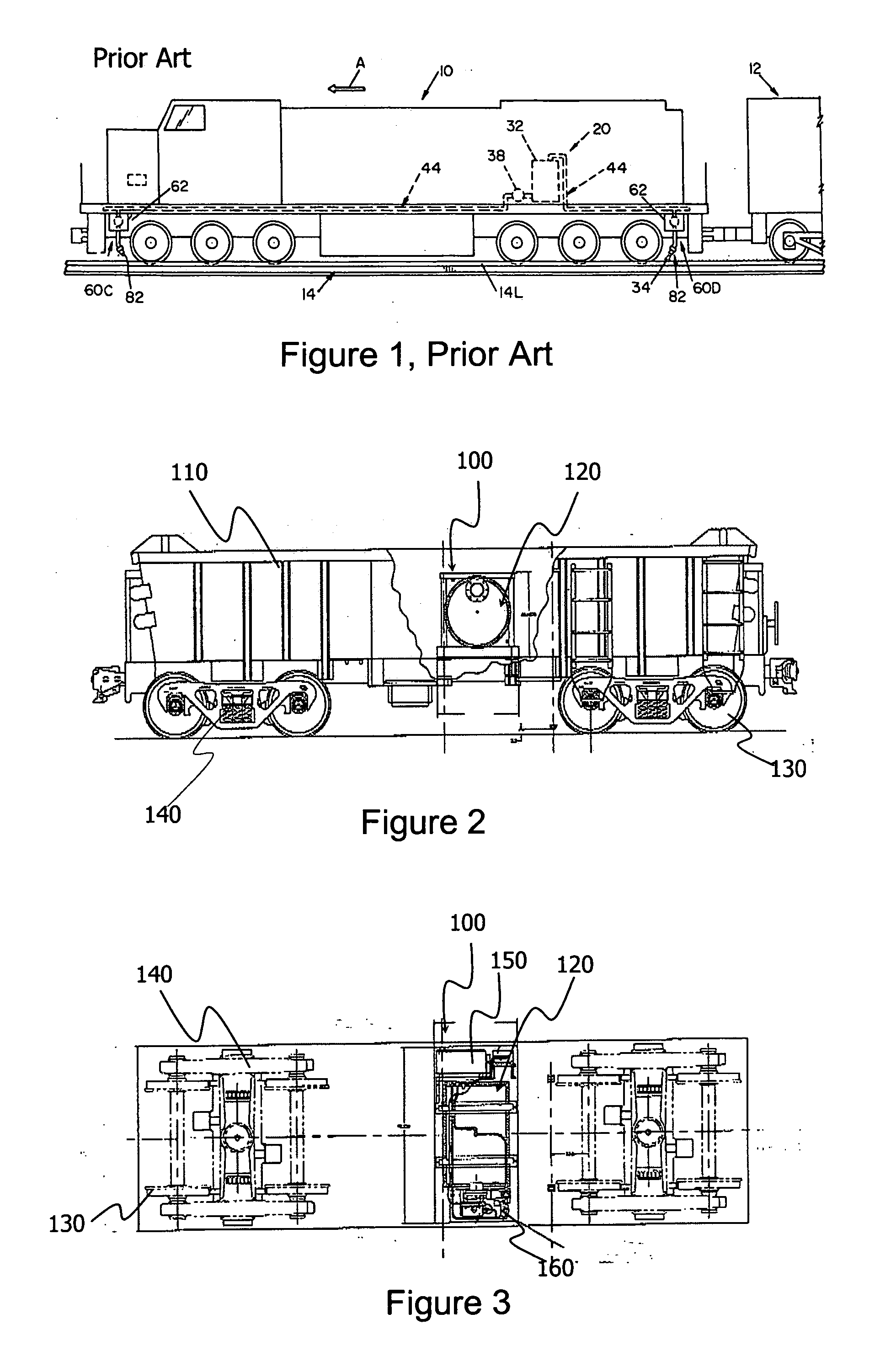
[0060] In railway industry, especially for the transport of freights, one or more locomotives can be physically connected together, with one locomotive designated as a lead locomotive and the others as trailing locomotives, this is usually called a ‘locomotive consist’. A ‘train’ or a ‘train consist’ means a combination of revenue generating cars (RGC; also called rail cars), and a locomotive consist. A rail car can be a passenger car or a freight car for example, but not limited to, a flat bed car, a refrigerated car, a bulk materials car for example an ore car, a chemical car, a seed or agricultural materials car, or a box car. Freight cars may unload by tipping. A common characteristic of a rail car is that it is not self-propelled. In contrast, a locomotive, or a mobile liquid composition delivery device such as the o...


PUM


Abstract

A method for applying a liquid composition to a rail surface is provided. This method involves supplying a liquid composition in one or more reservoirs on a rail car (revenue generating car), and applying the liquid composition from the one or more reservoirs to the rail surface.

Description

FIELD OF INVENTION [0001] The present invention relates to liquid composition application systems used in rail systems. BACKGROUND OF THE INVENTION [0002] The control of friction and wear of metal mechanical components that are in sliding or rolling-sliding contact is of great importance in the design and operation of many machines and mechanical systems. For example, many steel-rail and steel-wheel transportation systems including freight, passenger and mass transit systems suffer from the emission of high noise levels and extensive wear of mechanical components such as wheels, rails and other rail components. The origin of such noise emission, and the wear of mechanical components may be directly attributed to a number of factors: wheel and rail interaction characteristics; operating conditions including curvature, speed; and rail material strength including hardness. [0003] Mechanical friction at the wheel-rail interaction includes: a) friction on both tangent and curved tracks d...

Claims


Application Information

Patent Timeline
IPC IPC(8): B61C15/00B61K3/02
CPCB61K3/02
Inventor EADIE, DONCOTTER, JOHNELVIDGE, DAVE
Owner KELSAN TECH
Why Eureka
Try Eureka