Flexible rotor pole crossover for a generator

a generator and flexible technology, applied in the field of generators, can solve the problems of reducing the service life of the generator, and the inability to install the axially of the laminated rotor pole crossover, etc., and achieves the effects of less cost, excellent flexibility, and easy installation and manufactur

Active Publication Date: 2005-12-29
SIEMENS ENERGY INC
View PDF18 Cites 19 Cited by
  • Summary
  • Abstract
  • Description
  • Claims
  • Application Information

AI Technical Summary

Benefits of technology

[0010] It is another object of the present invention to provide a rotor pole crossover that can be placed into a limited space, such as connected into the first coil, as compared to prior art rotor pole crossover designs that are connected into the 5th or 6th coil.
[0011] The present invention is advantageous over brazing together individual laminations and provides a rotor pole crossover that can be used in restrictive and tight quarters, such as connecting into a first coil in those generators where any crossover connected to the first coil is necessarily small. The rotor pole crossover of the present invention has excellent flexibility when restricted to a single circumferential plane and is less expensive than traditionally laminated rotor pole crossovers that are also more difficult to install and manufacture and do not fit into available spaces, such as when connected into the first coil. Other prior art omega and U-shaped rotor pole crossovers would not provide the flexibility as compared to the rotor pole crossover of the present invention per unit of current carrying cross-section.
[0012] In one aspect of the present invention, a generator includes a shaft and rotor body supported by the shaft and defining poles. A winding is positioned around the shaft on the rotor body at the poles. A rotor pole crossover is preferably aligned to the shaft and connects ends of the winding between adjacent poles. The rotor pole crossover of the present invention includes a body member having a curved medial section and opposing legs extending outwardly from the curved medial section with free ends that connect to ends of the winding. At least one slit (i.e., slot) is formed within the curved medial section and adds flexibility to the rotor pole crossover.

Problems solved by technology

During generator operation, large centrifugal forces are exerted on the winding and rotor pole crossover, for example, by daily starts and stops to accommodate peak on and off electrical generation demands, and as a result, the rotor pole crossovers undergo stressful cyclic duty.
If rotor pole crossovers lack flexibility, they crack and cause a loss in the generator electrical field.
Unfortunately, a laminated rotor pole crossover usually cannot be installed axially.
If lap joints are connected to the winding end, any attempt to rotate the laminated rotor pole crossover for axial orientation would exert a greater load on the laminations and they would buckle.
Cracking would still be a problem.
This can be a problem with numerous older generation generators.
Also, laminated rotor pole crossovers are not practical because they are not installed axially.
Longer rotor pole crossovers, such as disclosed in the '097 patent, have enhanced flexibility because of their length, but crossovers limited in size would not have as much inherent flexibility even if the crossover included thickened and thinned sections.

Method used


Image

  • Flexible rotor pole crossover for a generator
  • Flexible rotor pole crossover for a generator
  • Flexible rotor pole crossover for a generator

Examples


Embodiment Construction

[0025] The present invention will now be described more fully hereinafter with reference to the accompanying drawings, in which preferred embodiments of the invention are shown. This invention may, however, be embodied in many different forms and should not be construed as limited to the embodiments set forth herein. Rather, these embodiments are provided so that this disclosure will be thorough and complete, and will fully convey the scope of the invention to those skilled in the art. Like numbers refer to like elements throughout, and prime notation is used to indicate similar elements in alternate embodiments.

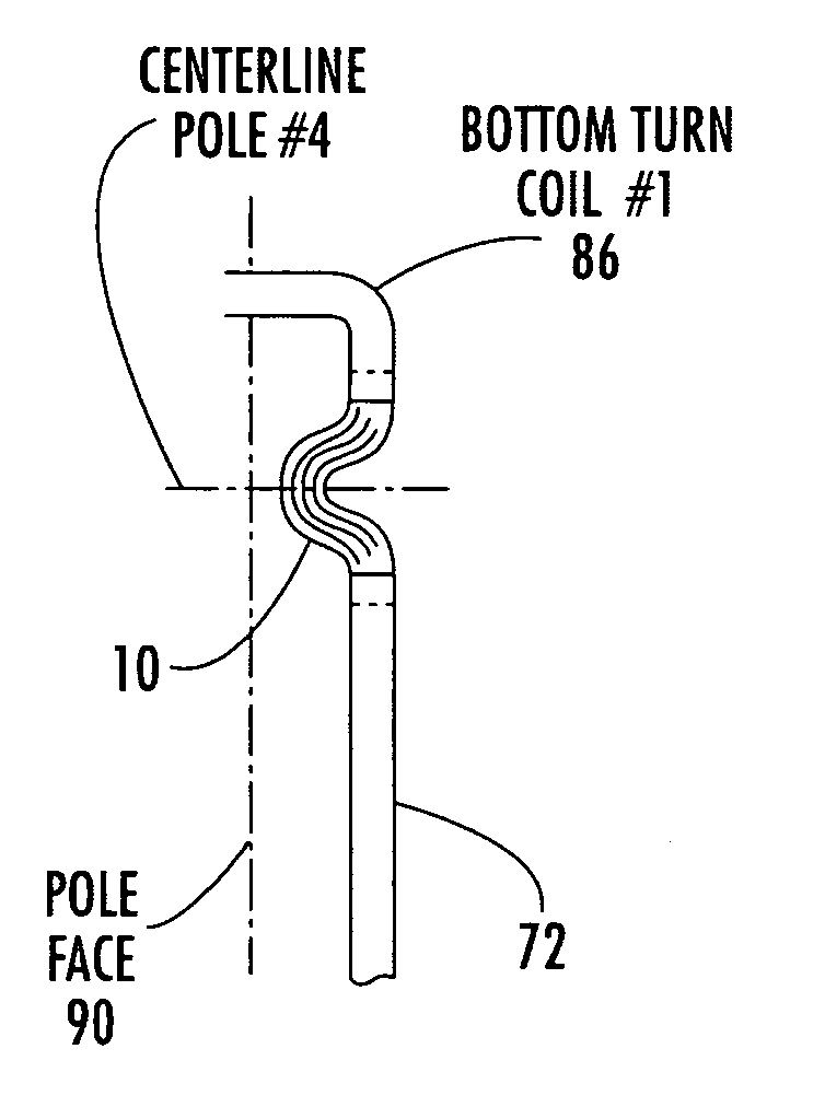
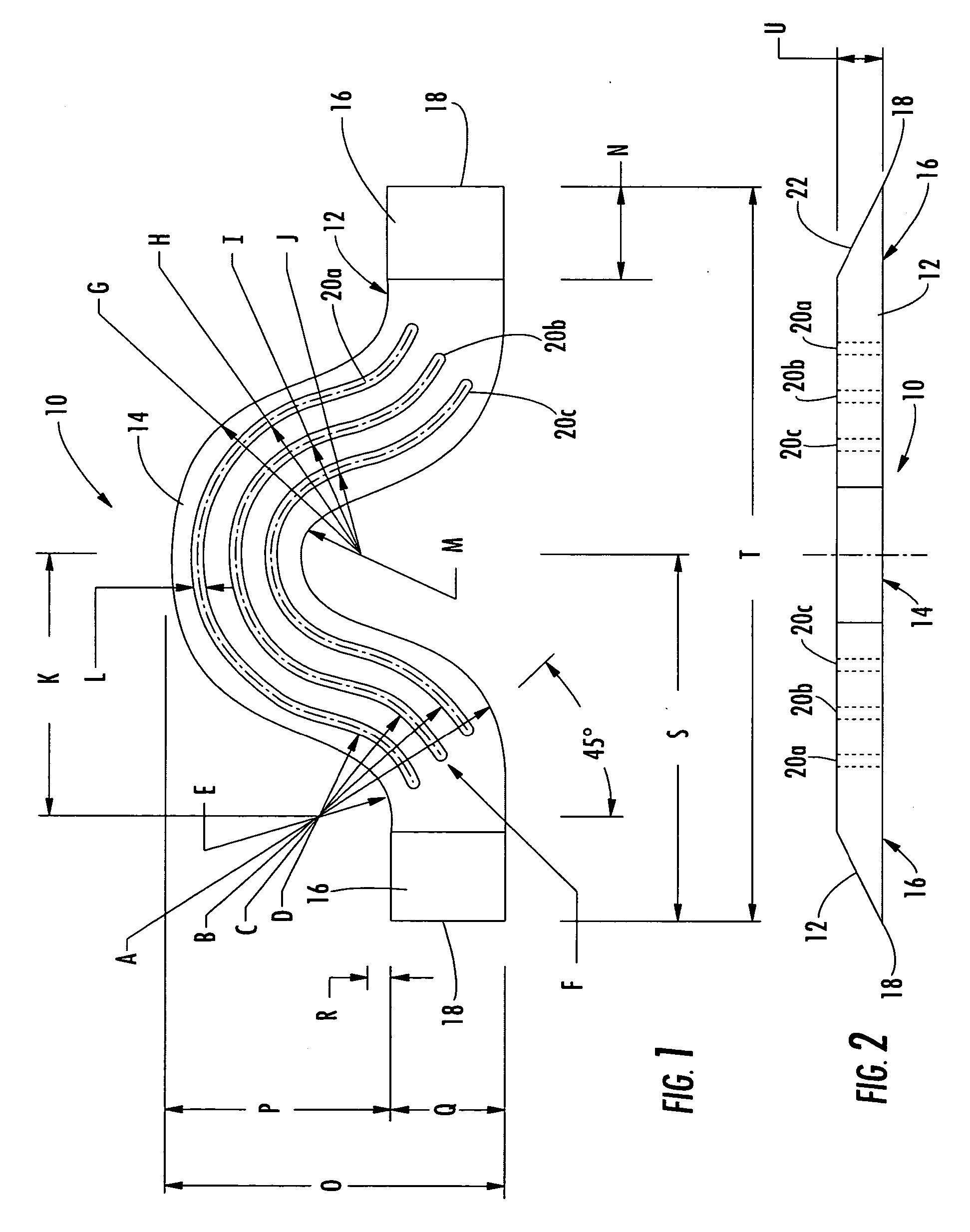
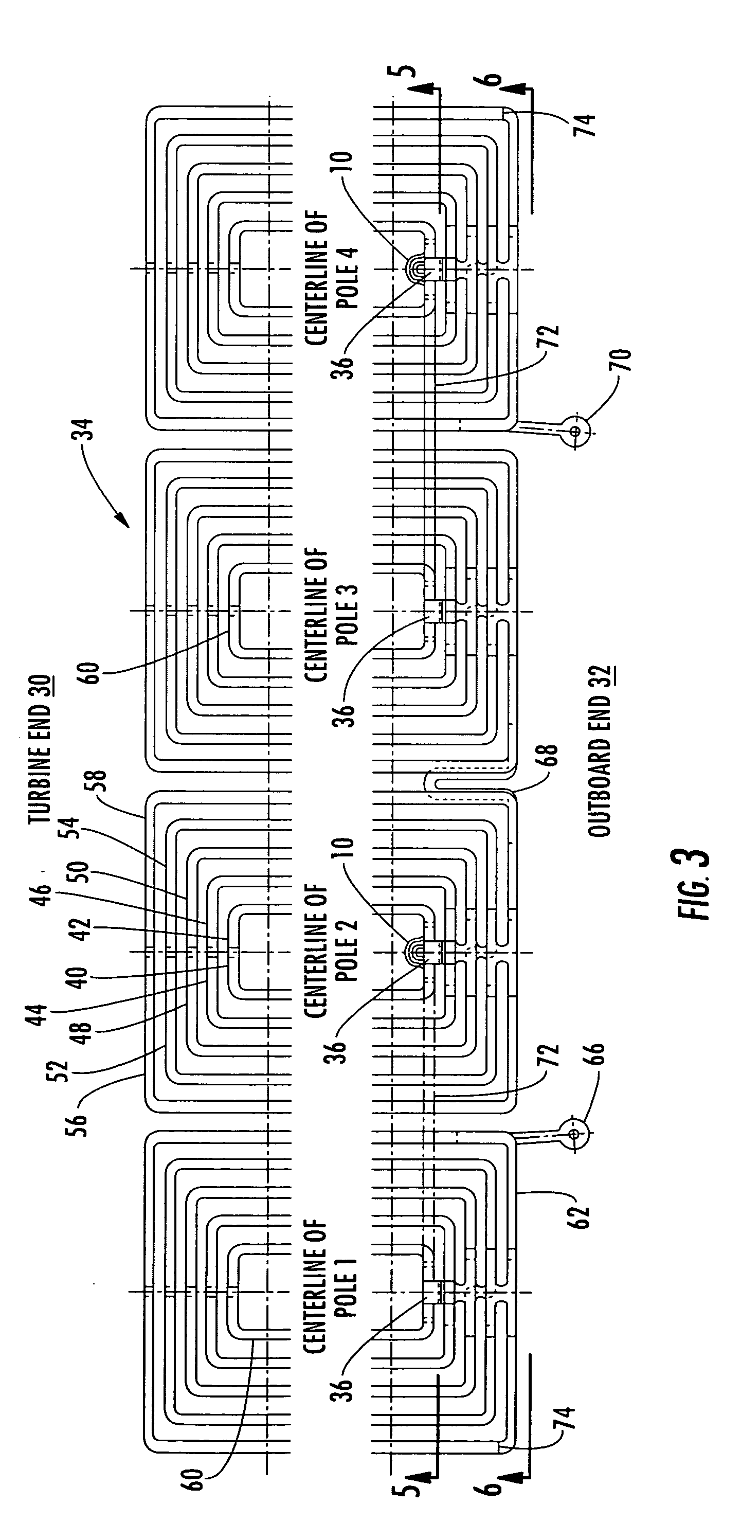
[0026] The present invention advantageously provides a rotor pole crossover 10 that can be positioned and connected in close confines and small spaces, such as connected to coil 1 of a winding in some older designed generators. FIGS. 1 and 2 illustrate the respective top plan and front elevation views of the rotor pole crossover 10 of the present invention. The rotor pole c...


PUM


Abstract

A generator includes a shaft and rotor body defining poles and a winding positioned around the shaft on the rotor body. A rotor pole crossover is aligned to the shaft and connects ends of the winding between adjacent poles. The rotor pole crossover includes a body member having a curved medial section and opposing legs extending outwardly from the curved medial section that connect to the ends of the winding. The curved medial section has at least one slot formed therein to add flexibility to the rotor pole crossover.

Description

FIELD OF THE INVENTION [0001] The present invention relates to generators, and more particularly, to rotor pole crossovers used in generators. BACKGROUND OF THE INVENTION [0002] A generator typically includes a shaft and rotor body supported by the shaft. The rotor body defines a number of poles, which vary in number depending on the design of the generator. For example, the speed at which the shaft rotates and frequency of electric current to be produced would impact the number of poles used in the generator. In a generator, copper wire is wound along the poles on the rotor body and referred to as the winding. In most large generators, for example, such as used in power generation plants and other similar generator applications, the cooper wire can be formed as flat, stiff, coiled copper bars. In some cases, the copper winding is about 1 by 0.25 inches in cross-section, as one non-limiting example. These coils forming the winding are often referred to as the conductors. [0003] The ...

Claims


Application Information

Patent Timeline
Patent Type & Authority Applications(United States)
IPC IPC(8): H02K1/00H02K3/50H02K3/52H02K11/00
CPCH02K3/522H02K3/505
Inventor SHORE, DAVIDKEATON, PHILLIP
Owner SIEMENS ENERGY INC
Why Eureka
Try Eureka