

Radar sensor
a sensor and sensor technology, applied in the field of radar sensors, can solve the problems increasing the size of the antenna, and reducing the transmitting characteristics of the sensor, etc., and achieve the effect of reducing the transmission power of the two outer channels
- Summary
- Abstract
- Description
- Claims
- Application Information
AI Technical Summary
Benefits of technology
Problems solved by technology
Method used
Image

Examples
Embodiment Construction
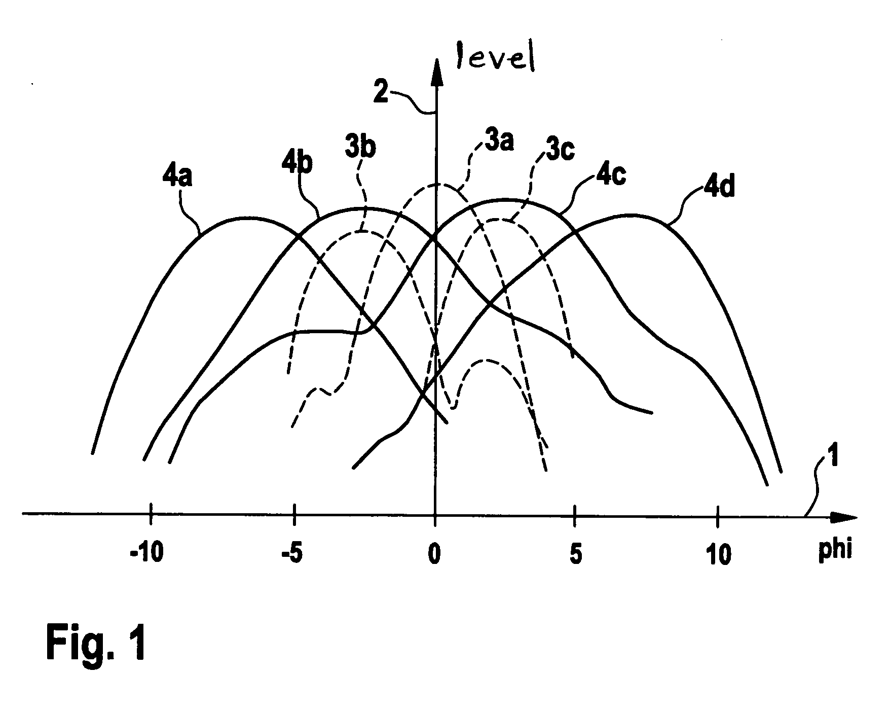
[0015]FIG. 1 shows the transmit and receive diagram of two radar sensors. Azimuth angle phi of the radar sensor is plotted on abscissa 1, and the voltage level of the individual receive channels of the sensors is illustrated on the ordinate. A first radar sensor, which is configured without the device according to the present invention, is indicated by the three curves 3a, 3b and 3c, which are drawn in as dashed lines. This radar sensor is a three-beam radar sensor which has a dielectric lens to focus and parallelize the microwave radiation, the lens having a comparatively large diameter of 75 mm, for instance. This dielectric lens parallelizes and focuses the microwave radiation of the three patch antennas, one individual antenna being provided for each transmit and receive channel. Furthermore, FIG. 1 shows the transmit and receive diagram of an additional radar sensor which, for one, has four channels, i.e., four transmit and receive antennas are present which may preferably be i...
PUM
 Abstract
Description
Claims
Application Information