Image processing apparatus

Inactive Publication Date: 2005-12-29
CANON KK
View PDF22 Cites 15 Cited by
  • Summary
  • Abstract
  • Description
  • Claims
  • Application Information

AI Technical Summary

Benefits of technology

[0011] According to the invention, since the feeding roller, the separation unit and the conveyance path for separating and conveying the document and the recording medium can be employed in common for the image processing apparatus, which includes reading me

Problems solved by technology

However, compared with another conveying means and a conveyance path that are employed to convey a document and a recording medium, merely the delivery roller 305 is employed in common, and the reduction in the size and the cost of the apparatus is unsati

Method used


Image

  • Image processing apparatus
  • Image processing apparatus
  • Image processing apparatus

Examples


Embodiment Construction

[0023] The embodiment of the present invention will now be described in detail while referring to the accompanying drawings. However, as to the scope of the invention, the sizes, materials, shapes and relative positions of the components are not limited to those described in this embodiment, unless especially so designated.

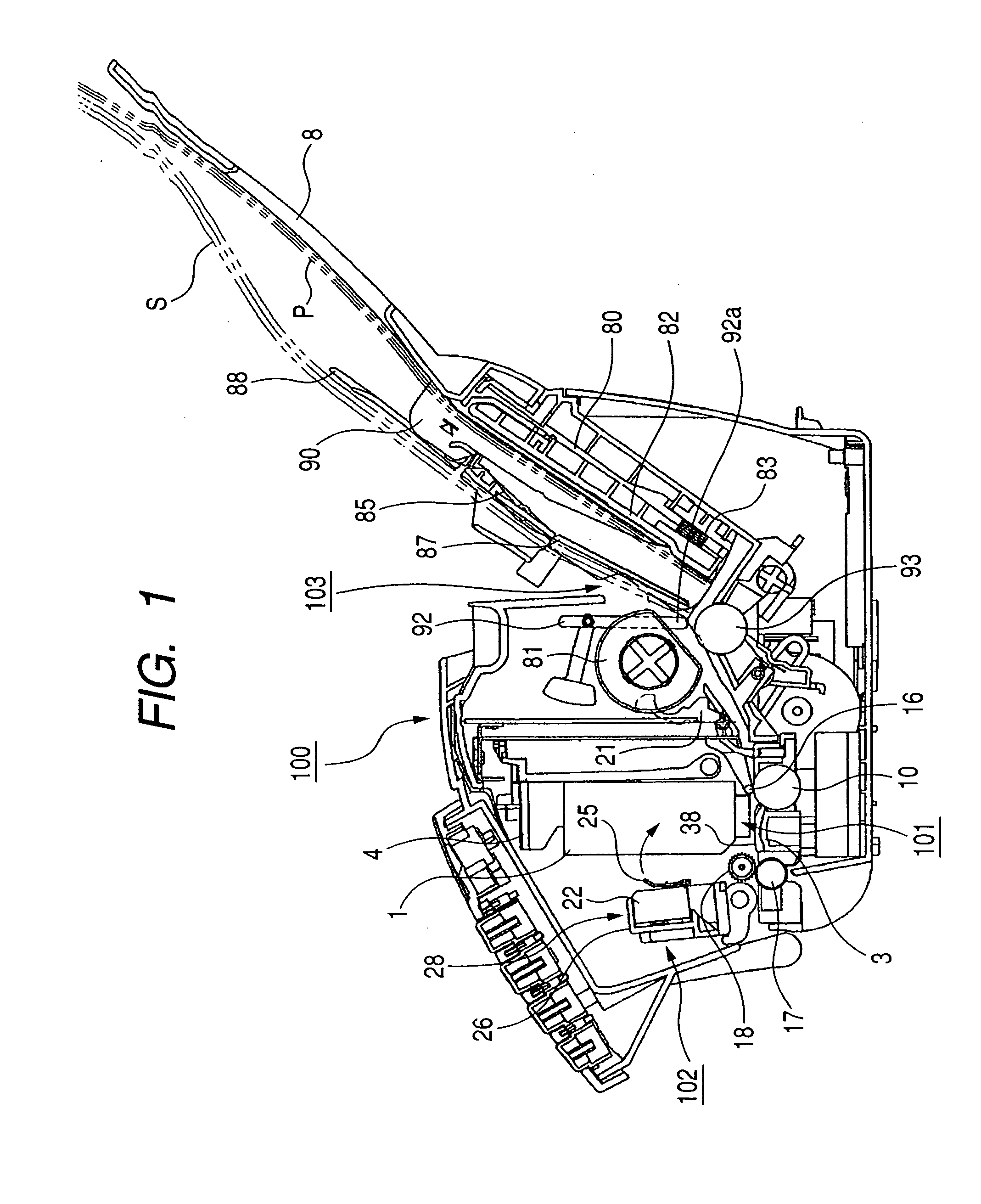
[0024]FIG. 1 is a cross sectional view of the configuration of an image processing apparatus according to the embodiment of the present invention, using a facsimile machine as an example. A facsimile machine 100 in FIG. 1 comprises: an image recording unit 101, including a cartridge 1, that is a recording means example; an image reading unit 102, including an image reader 28, that is a reading means example; and an automatic feeder 103, which separates a plurality of recording medium P, or a plurality of documents S, and feeds each recording medium P or each document S that has been set for the image recording unit 101 or the image reading unit 102.

[0025] Downst...


PUM

PropertyMeasurementUnit
Fractionaaaaaaaaaa
Widthaaaaaaaaaa
Distanceaaaaaaaaaa

Abstract

The typical configuration of an image processing apparatus includes a document stacking means on which documents are stacked, a recording medium stacking means on which recording medium are stacked, and a feeding roller for feeding documents or recording medium from the document stacking means or the recording medium stacking means. The feeding roller is located above the recording medium stacking means, and at least the lower end of the recording medium stacking means is movable in the direction approaching or moving away from the feeding roller. The document stacking means is attached above and substantially parallel to the recording medium stacking means, at a predetermined interval. Further, the document stacking means does not have a support portion at a location corresponding to the feeding roller, and is moved as the recording medium stacking means is moved.

Description

BACKGROUND OF THE INVENTION [0001] 1. Field of the Invention [0002] The present invention relates to the configuration of an image processing apparatus, such as a facsimile machine, that includes a conveyance path used in common for a document and a recording medium. [0003] 2. Related Background Art [0004] An image processing apparatus, such as a facsimile machine wherein part of a conveyance path is employed in common for a document and a recording medium, has been proposed for size and cost reduction purposes. [0005] One example of such a configuration is shown in FIG. 11. The image processing apparatus in FIG. 11 comprises: an ASF unit 301, for separating and individually conveying recording medium in a stack stacked on a stacking tray; an ADF unit 302, for separating and individually conveying document sheets in a stack stacked therein; an auxiliary convey roller 303, for conveying a recording medium or a document conveyed by the ASF unit 301 or the ADF unit 302; a main convey r...

Claims


Application Information

Patent Timeline
IPC IPC(8): B41J13/10B65H3/06B65H3/52B65H3/56G03G15/00
CPCB41J13/103B65H3/0638B65H3/0661B65H3/56B65H2301/4225B65H2301/4222B65H2405/113G03G15/60G03G15/6502B65H3/565B65H2404/1112B65H1/08B65H5/06
Inventor TERASHIMA, HIDEYUKISUZUKI, YOSHIAKIAWAI, TAKASHI
Owner CANON KK
Why Eureka
Try Eureka