Steering control device

Active Publication Date: 2006-04-20
NSK LTD
View PDF5 Cites 8 Cited by
  • Summary
  • Abstract
  • Description
  • Claims
  • Application Information

AI Technical Summary

Benefits of technology

[0013] An object of the invention is to provide a compact mechanical steering angle regulating mechanism in which an allowable rotation range of a steering wheel is made ±180 deg

Problems solved by technology

In the SBW control, since the steering reaction force is generated by the electric motor, when the turning actuator is put in the maximum turning position, it has been difficult to prevent the rotation of the steering wheel by the electric motor.
For example, when a lock state occurs, a large output motor is required in order to generate the steering reaction force against the steering torque by the driver, and since a large current flows through the motor, there has been a fear that the motor is burnt by overheating.
However, when current is limited in order t

Method used


Image

  • Steering control device
  • Steering control device
  • Steering control device

Examples


first embodiment

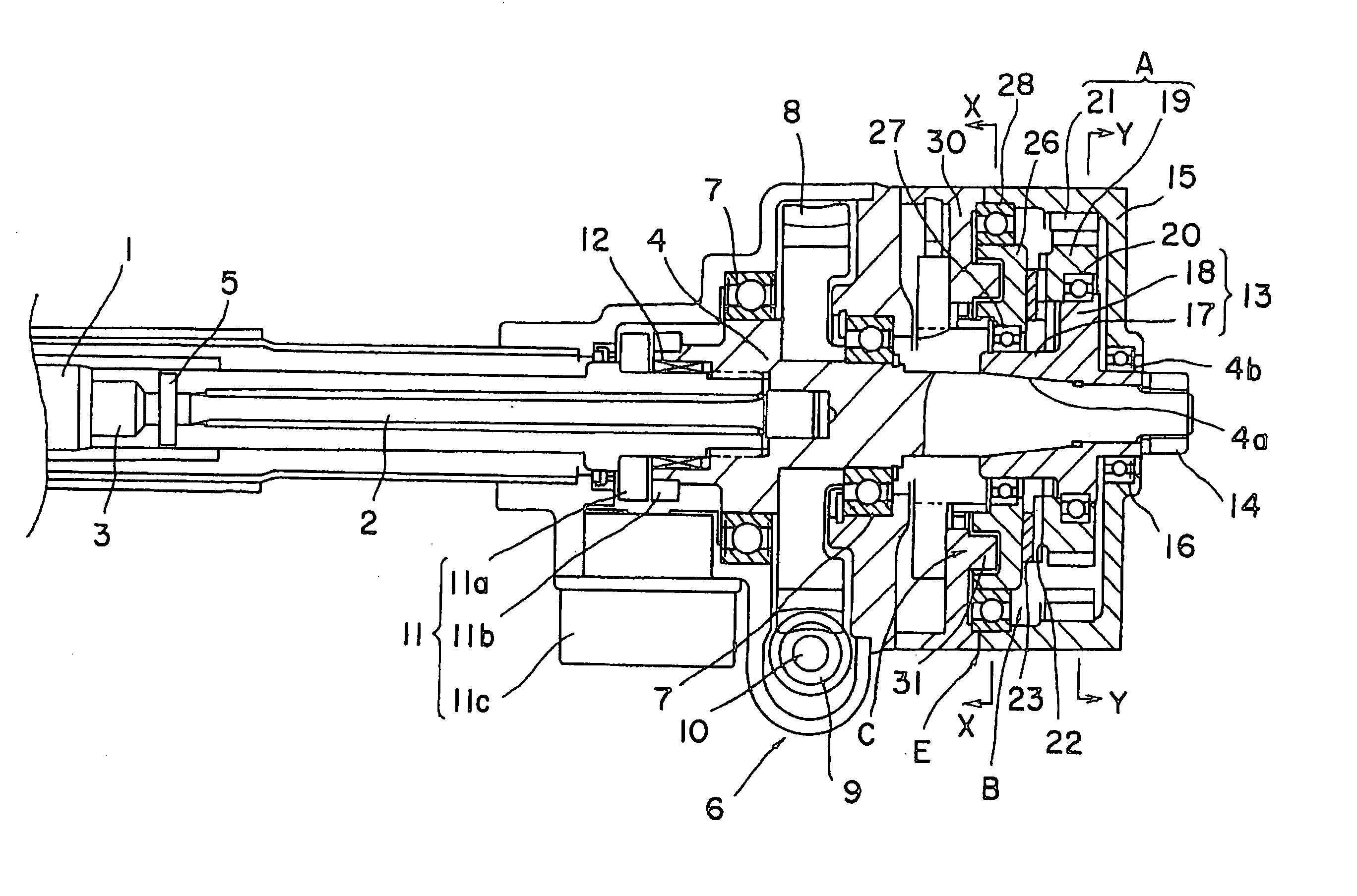
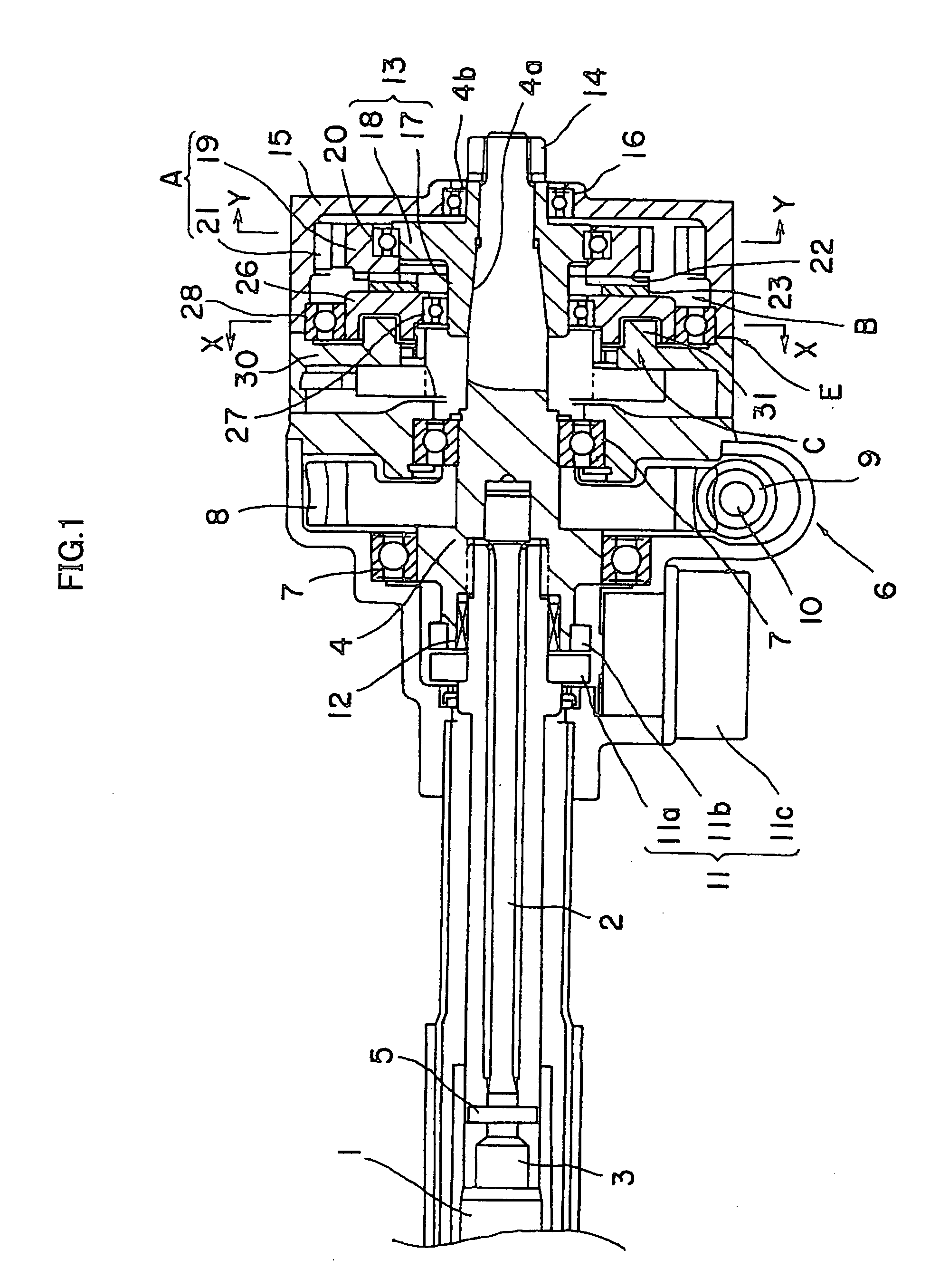
[0058]FIG. 1 shows a rough structure of a steering system according to the invention, and an input shaft 3 and a substantially cylindrical output shaft 4 are coupled to an output end side of a steering shaft 1 through a torsion bar 2. One end of the torsion bar 2 is fixed to the input shaft 3 through a pin 5, and the other end is pressed in and fixed by the output shaft 4.

[0059] Besides, a speed reducer 6 is supported by a pair of ball bearings 7 and 7 at an outer periphery of the output shaft 4. The speed reducer 6 includes a worm wheel 8 pressed in and fixed by the outer periphery of the output shaft 4, a worm 9 engaging with the worm wheel 8, and a motor (not shown) in which the worm 9 is attached to a rotation shaft 10, and the drive force of the motor is reduced and transmitted to the output shaft 4 through the speed reducer 6.

[0060] An angle-torque sensor 11 is disposed at a steering wheel side (left in FIG. 1) of the speed reducer 6, and the angle-torque sensor 11 includes a...

second embodiment

[0071] Next, the invention will be described.

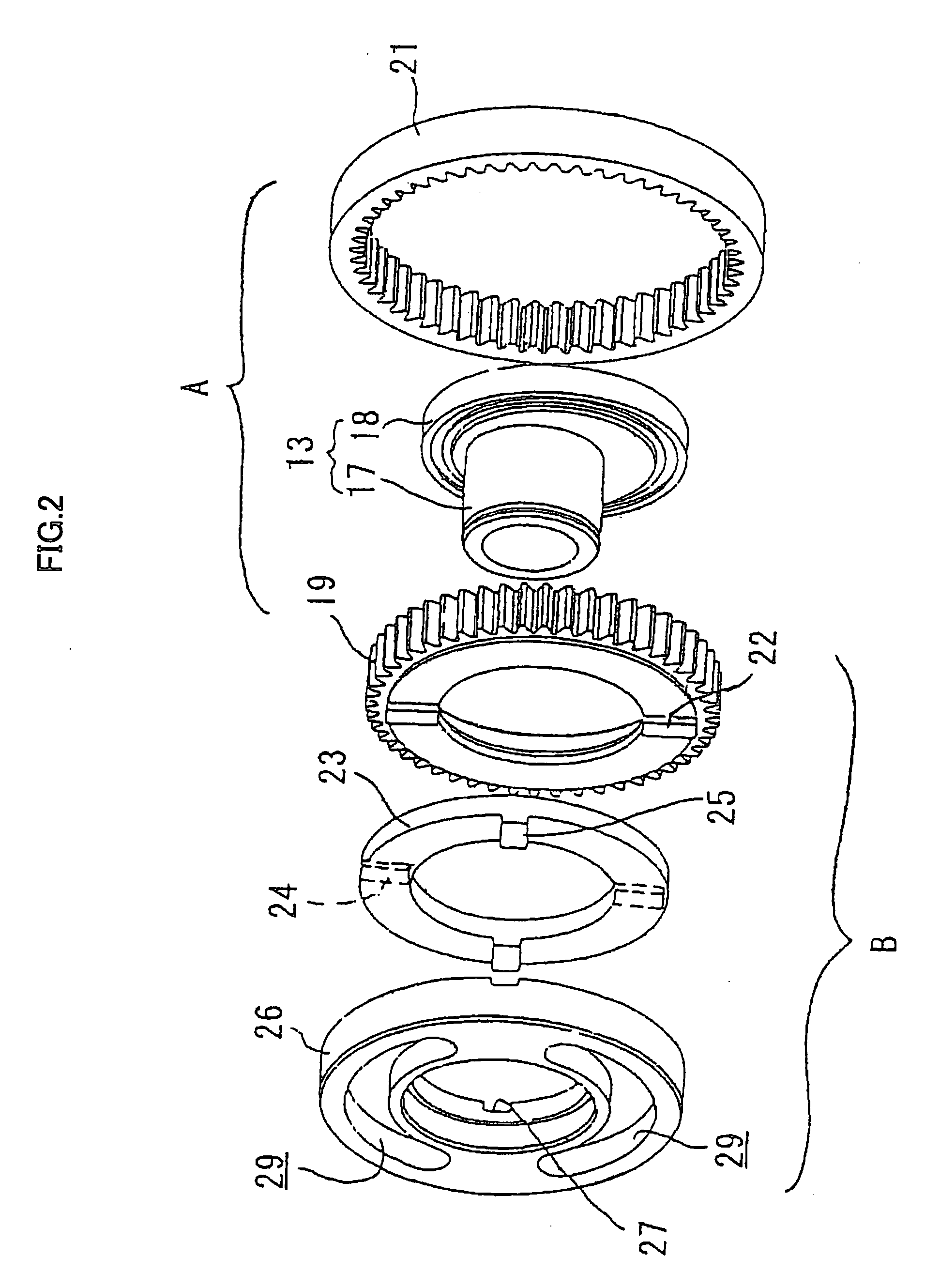
[0072]FIG. 5 shows a rough structure of a steering system according to the second embodiment of the invention, and the same members as the first embodiment are denoted by the same reference characters and their explanation will be omitted. In the drawing, a hub 13 is fitted onto an end of an output shaft 4 coupled to a steering wheel. The hub 13 positions an Oldham coupling mechanism B by a pair of ball bearings 20 and 27.

[0073] A disk spring 41 as an elastic body to urge toward the end side (right in FIG. 5) is wound around the ball bearing 27 disposed at the output shaft 4, the ball bearing 27 is pressed to the end side (right in FIG. 5) by this disk spring 41, and working torque to the positioning of the Oldham coupling mechanism B is made certain.

[0074] In general, in the steering control apparatus, since mechanical coupling is not made from a steering wheel to a turning wheel (tire), when friction acting on the Oldham coupling mech...

third embodiment

[0075] Next, the invention will be described.

[0076]FIG. 6 shows a rough structure of a steering system according to the third embodiment, and the same members as the first embodiment are denoted by the same reference characters and their explanation will be omitted. In the drawing, a fitting hole 51a is formed in a housing 51 of a reaction force imparting mechanism, and a projection 52 extending toward the end side (right in FIG. 6) is fitted to the fitting hole 51a. The projection 52 is engaged with a recess groove 29 of a rotation disk 26 extending in the peripheral direction within a predetermined rotation range, and a rotation regulating mechanism C to regulate the rotation of the rotation disk 26 is comprised of the engagement between the projection 52 and the recess groove 29.

[0077] By this, in the third embodiment, like the first and the second embodiments, an end face of a housing 15 of the rotation regulating mechanism C at a steering wheel side can be eliminated, and the ...


PUM


Abstract

A steering control apparatus in which a steering shaft coupled to a steering wheel is mechanically separated from a turning mechanism to turn a turning wheel, a steering angle of the steering wheel is detected, and the turning mechanism turns the turning wheel by a turning angle corresponding to the steering angle, includes a hypercycloidal mechanism including an external tooth gear revolving in a housing according to rotation of the steering wheel, an Oldham coupling mechanism to extract only a self-rotating movement in a rotation movement of the external tooth gear as a self-rotating movement of a rotation disk, and a rotation regulating mechanism by engagement between a groove formed in the rotation disk and a projection projecting from the housing. Then, a compact mechanical steering angle regulating mechanism is provided in which an allowable rotation range of the steering wheel is made ±180 degrees or more, and a low output and low capacity motor is used, and reduction in size and in cost of the apparatus is realized.

Description

BACKGROUND OF THE INVENTION [0001] 1. Technical Field [0002] The present invention relates to an improvement of a steering control apparatus which electrically controls steering of a steering wheel by using an electric motor. [0003] 2. Prior Art [0004] In recent years, a steering control apparatus is proposed in which a steering shaft coupled to a steering wheel is mechanically separated from a turning mechanism to turn a turning wheel, and the interlocking control of these is electrically performed by SBW (Steer By Wire) control (hereinafter referred to as SBW control). [0005] In this steering control apparatus, an operation direction and a steering angle of the steering wheel are detected, a turning angle corresponding to the steering angle in the operation direction is given, and steering corresponding to the operation of the steering wheel is performed. [0006] At that time, an electric motor is driven according to the operation amount of the steering wheel, turning force of a tu...

Claims


Application Information

Patent Timeline
IPC IPC(8): B62D5/00F16H1/32
CPCB62D5/006F16H1/32F16H2001/326
Inventor CHIKARAISHI, KAZUO
Owner NSK LTD
Why Eureka
Try Eureka