Gas compressor

Inactive Publication Date: 2005-12-29
CALSONIC COMPRESSOR INC
View PDF11 Cites 3 Cited by
  • Summary
  • Abstract
  • Description
  • Claims
  • Application Information

AI Technical Summary

Benefits of technology

[0009] Under the circumstances, it is an object of the present invention to provide a gas compressor which can make a housing more compact without increasing the weight of the housing and more easily prevent internal leakage as compared with the conventional gas compressor.
[0013] The discharge passage receiving the compressed gas discharged through the discharge outlet is not opened to the outer periphery of the cylinder, but is formed in the thick portion of the cylinder along with a center axis of the cylinder chamber. Accordingly, the pressure of the refrigerant compressed in the compressing chamber does not act as an internal pressure directly upon that portion of the housing as covering the outer periphery of the cylinder. Therefore, that portion of the housing as covering the outer periphery of the cylinder can be relatively strengthened without increasing the thickness of this portion.
[0014] Further, since the refrigerant to be compressed is guided into the compressing chamber from the suction chamber through the suction inlet opened in the peripheral wall of the cylinder via the suction passage formed along the outer periphery of the cylinder, the low-pressure path including the suction passage can be relatively easily and assuredly separated from the high-pressure path including the discharge passage. Thus, the internal leakage of the compressed refrigerant can be assuredly prevented by the relatively simple construction.
[0019] Since the rotor can be rotated at a higher speed in the motor-driven gas compressor as compared with the gas compressor in which the rotor is rotated by rotary force of an engine mounted in a vehicle, the invention is more advantageous for a CO2 gas compressor which requires higher pressure refrigerant as compared with R134a. The present invention is also advantageous in miniaturization and weight reduction of the gas compressor using such a high-pressure refrigerant.
[0021] Therefore, according to the present invention, high discharge pressure is prevented from acting as the internal pressure upon the housing at the outer periphery of the cylinder, and the internal leakage of the compressed gas from the high-pressure side to the low-pressure side can be assuredly prevented. Therefore, the housing can be made compact without causing increased weight of the housing and the internal leakage can be assuredly prevented.

Problems solved by technology

Consequently, in order to withstand such a high pressure, the housing 2 is made thick, so that the increased thickness may cause the larger dimension and increased weight of the housing.
Further, according to the conventional structure in which the discharge pressure acts upon the outer peripheral portion of the cylinder, it was not easy to assuredly prevent internal leakage from occurring due to the leakage of the high pressure at the outer peripheral portion of the cylinder toward a low-pressure side such as the suction passage.

Method used


Image

  • Gas compressor
  • Gas compressor
  • Gas compressor

Examples


Embodiment Construction

[0028] In the following, the present invention will be explained along with an embodiment shown in the drawings.

[0029] The gas compressor according to the present invention is to be applied to an air conditioner mounted on an automobile, for example. This gas compressor forms a refrigerant-circulating path for cooling cycles together with a condenser, an expansion valve, an evaporator, etc. conventionally well known as the constituent elements of the air conditioner.

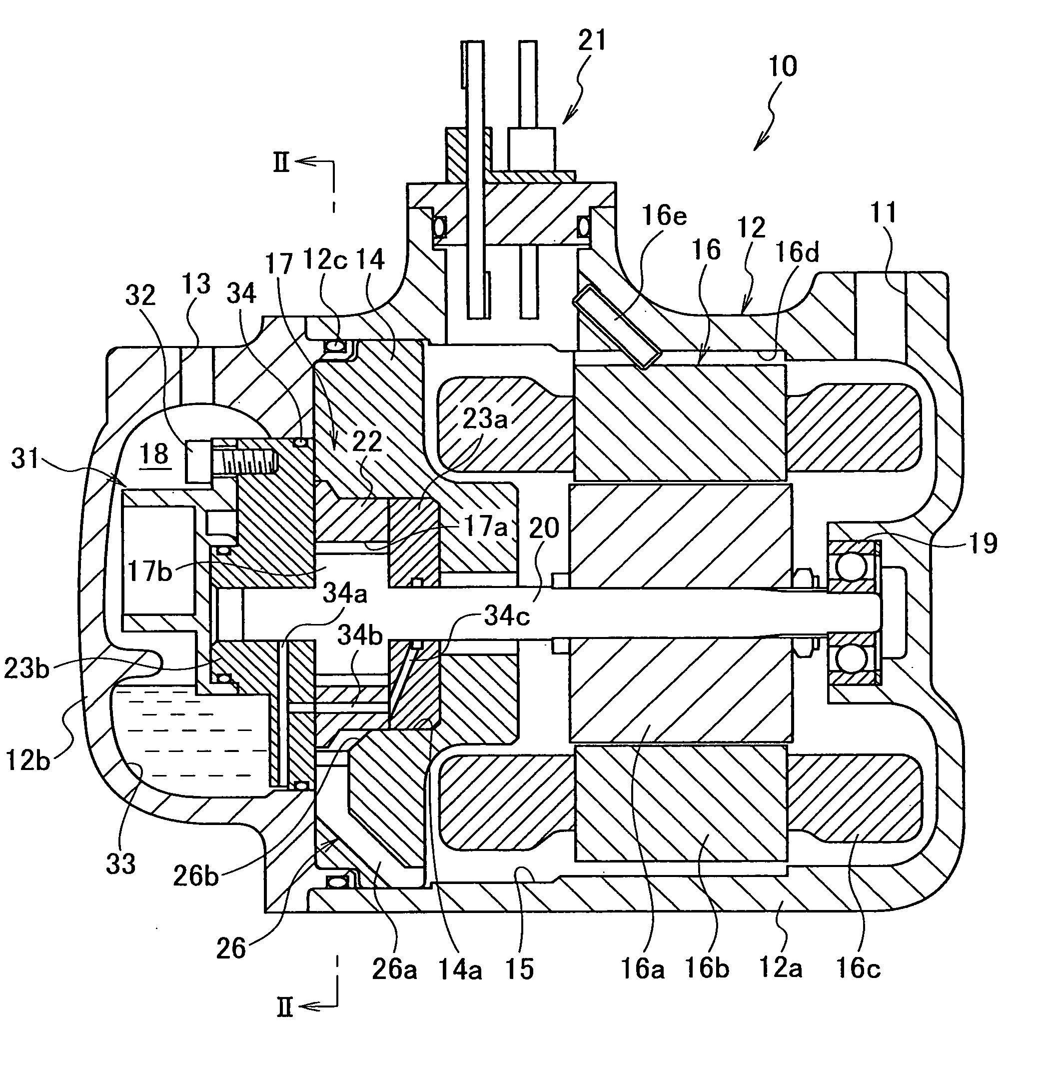
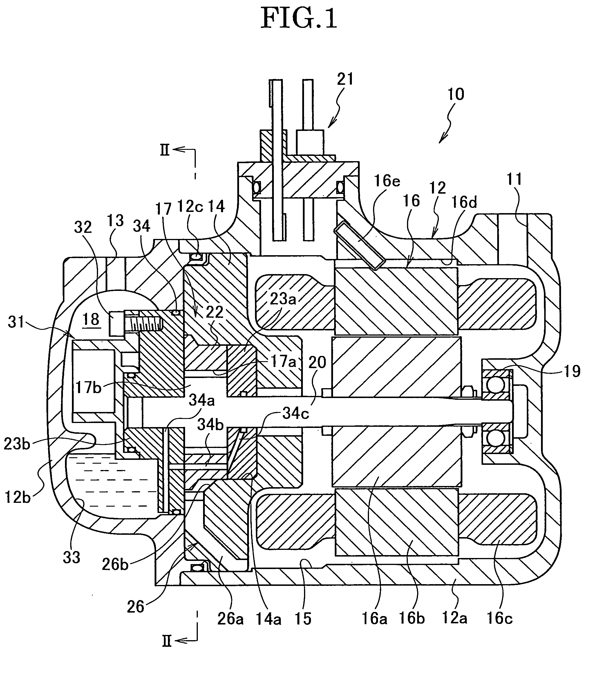
[0030] In the embodiment shown in FIG. 1, the gas compressor 10 according to the present invention comprises a two-split type housing 12 composed of a cylindrical front housing member 12a having one end opened and a cylindrical rear housing member 12b closing the opened one end of the front housing member 12a. The housing members 12a and 12b are assembled together in a cylindrical form as a whole. The front housing member 12a is formed with a suction port 11 to be connected to the evaporator (not shown). The rear housi...


PUM


Abstract

A gas compressor includes a housing with suction and discharge ports, and a gas-compressing mechanism housed in the housing to compress a gas sucked through the suction port and discharge the compressed gas via the discharge port. The mechanism includes a cylinder defining a cylinder chamber with a circular or elliptical cross-sectional shape. The cylinder has a suction inlet and a discharge outlet. The suction inlet and the discharge outlet are opened in a peripheral wall of the cylinder chamber. A suction passage is formed along an outer periphery of the cylinder corresponding to a peripheral direction of the cylinder chamber. A discharge passage extends inside a thick portion of the cylinder along a center axis of the cylinder chamber. The suction inlet communicates with the suction port via the suction passage. The discharge outlet communicates with the discharge port via the discharge passage.

Description

BACKGROUND OF THE INVENTION [0001] 1. Field of the Invention [0002] The present invention relates to a gas compressor which is to be favorably assembled into a refrigerating machine or an air conditioner as a refrigerant compressor. Particularly, the invention favorably relates to a motor-driven gas compressor into which an electric motor is assembled as a driving source for a gas-compressing mechanism. [0003] 2. Related Art Statement [0004] Heretofore, a vane rotary type gas compressor is used as the gas compressor of this type (For example, see JP-A 2003-254244). As shown in FIG. 4, a compressing mechanism 3 is housed in a housing 2 of such a vane rotary type gas compressor 1. The housing 2 is provided with a suction port and a discharge port not shown. The compressing mechanism 3 has a cylinder 4 and a rotor 5 rotatably housed in the cylinder. The cylinder 4 defines a cylinder chamber 6 having an elliptical cross-sectional shape. In the cylinder chamber 6, the rotor 5 is provided...

Claims


Application Information

Patent Timeline
IPC IPC(8): F04C18/344F04C23/00
CPCF04C18/3441F04C18/3446F04C2210/1072F04C29/12F04C2210/1027F04C23/008
Inventor YODA, SEIICHIROSHI, YONGWEI
Owner CALSONIC COMPRESSOR INC
Why Eureka
Try Eureka