
System for diagnosing reagent solution quality and emissions catalyst degradation

a technology of emissions catalyst and reagent solution, which is applied in the direction of position/direction control, special data processing applications, and combination devices, etc., can solve the problems of contamination, over-concentration, and the possibility of solution being under-concentrated

Active Publication Date: 2005-12-29
CUMMINS INC
View PDF32 Cites 33 Cited by
  • Summary
  • Abstract
  • Description
  • Claims
  • Application Information

AI Technical Summary

Benefits of technology

[0005] The present invention may comprise one or more of the following features and combinations thereof. A system and method for determining reagent solution quality may comprise a reagent solution source for supplying the reagent solution to an emissions catalyst configured to receive a NOx-containing gas therethrough, means for determining a NOx flow rate corres...

Problems solved by technology

Prior to dispensing the reagent solution into the exhaust gas stream, there may be opportunities for the solution to become under-concentrated, over-concentrated and / or exposed to contaminants as a result of manufacturing concentration variability, tampering, accidental introduction of improper fluid, mechanical failures or undesirable mechanical operating conditions, and / or environmental degradation.

Method used


Image

  • System for diagnosing reagent solution quality and emissions catalyst degradation
  • System for diagnosing reagent solution quality and emissions catalyst degradation
  • System for diagnosing reagent solution quality and emissions catalyst degradation

Examples


Embodiment Construction

[0025] For the purposes of promoting an understanding of the principles of the invention, reference will now be made to a number of illustrative embodiments illustrated in the drawings and specific language will be used to describe the same.

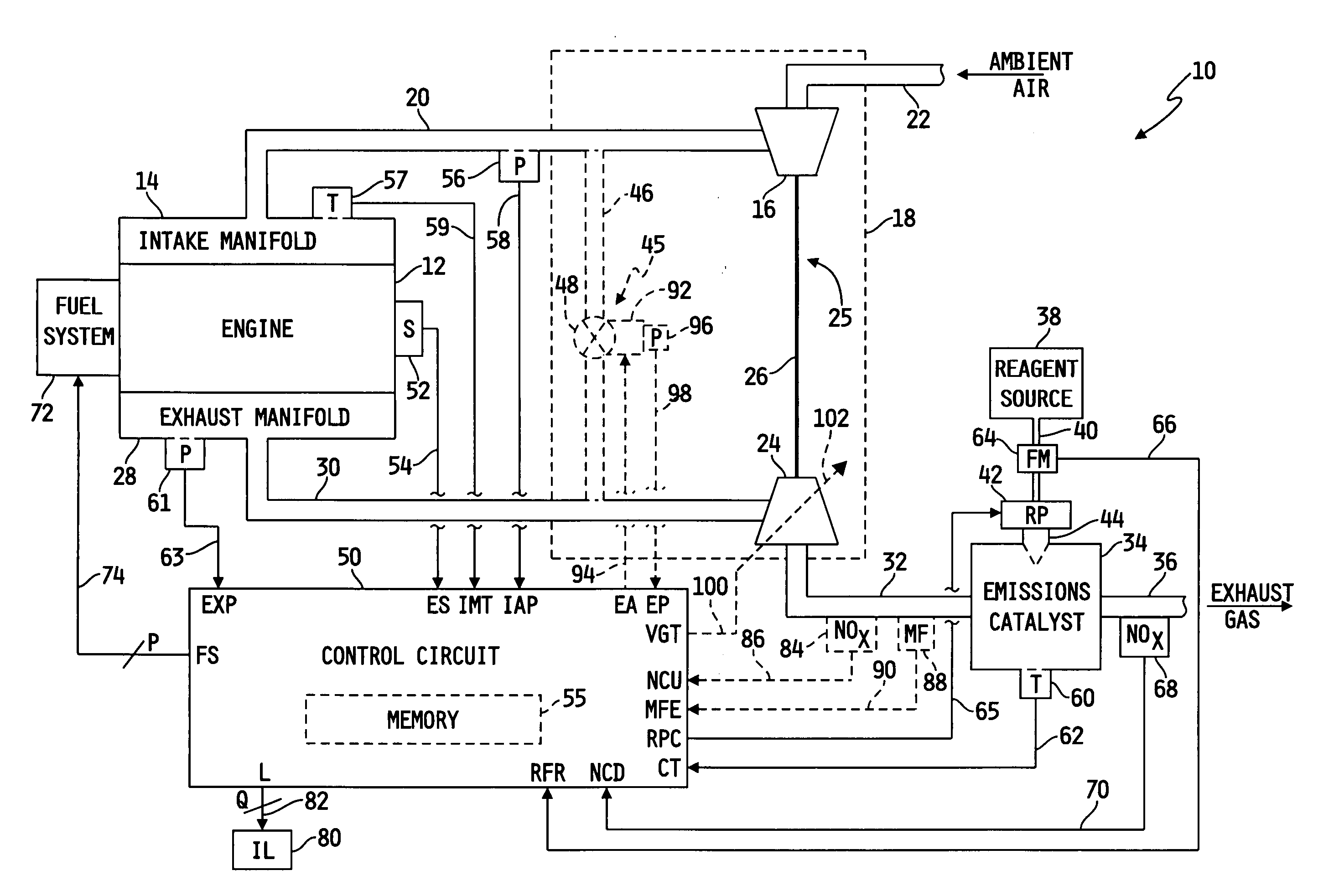
[0026] Referring to FIG. 1, a block diagram of one illustrative embodiment of a system 10 for diagnosing reagent solution quality and emissions catalyst degradation is shown. The system 10 includes an internal combustion engine 12 having an intake manifold 14 fluidly coupled to an intake pipe or conduit 20 for receiving fresh air. An exhaust manifold 28 of the engine 12 is fluidly coupled to an exhaust pipe or conduit 30, and NOx-containing exhaust gas resulting from the combustion process within the engine 12 is directed away from the exhaust manifold 28 via the exhaust pipe or conduit 30. The system 10 may or may not include an air handling system 18, as shown in phantom in FIG. 1. It will be noted that although the internal combustion engine ...


PUM

PropertyMeasurementUnit
Timeaaaaaaaaaa
Flow rateaaaaaaaaaa
Threshold limitaaaaaaaaaa

Abstract

A system for determining a reagent solution quality indicator includes a reagent solution source for supplying the reagent solution to an emissions catalyst configured to receive a NOx-containing gas therethrough, means for determining a flow rate of NOx reduced from the gas by the catalyst, means for determining a flow rate of the reagent solution into the catalyst, and a control circuit determining the reagent solution quality indicator as a function of the NOx flow rate and the reagent solution flow rate. The system may additionally be configured to diagnose reagent solution quality by configuring the control circuit to monitor the reagent solution quality indicator over time and produce a fault value if the reagent solution quality indicator crosses a reagent quality indicator threshold, and to diagnose the catalyst by producing another fault value if the catalyst capacity point falls outside of a catalyst capacity point threshold.

Description

FIELD OF THE INVENTION [0001] The present invention relates generally to systems for diagnosing reagent solution quality and emissions catalyst degradation, and more specifically to such systems for diagnosing reagent solution quality and emissions catalyst degradation as functions of NOx and reagent solution flow rates. BACKGROUND OF THE INVENTION [0002] Systems for treating exhaust gas produced by an internal combustion engine to reduce exhaust gas emissions in the form of particulates and / or NOx are generally known. Such exhaust gas “aftertreatment” systems may include a selective catalytic reduction system for the purpose of reducing the NOx level of the exhaust gas below a specified maximum NOx level. [0003] A selective catalytic reduction system, or SCR, typically includes a catalytic reducing agent, or reagent, in the form of a reagent solution that is controllably dispensed into the exhaust gas stream produced by the engine before entering a conventional SCR catalyst. The SC...

Claims


Application Information

Patent Timeline
IPC IPC(8): F01N3/20F02B37/18F02B37/22F02B37/24G01N21/76
CPCF01N3/2066Y10T436/179228F01N2550/03F01N2550/05F01N2610/02F02B37/18F02B37/22F02B37/24F02D41/1462F02D41/1465Y02T10/24Y10T436/173845Y10T436/12Y10T436/175383Y10T436/177692F01N2550/02Y02T10/12
Inventor WILLS, J. STEPHENANDREWS, ERIC B.
Owner CUMMINS INC
Learn More