System and method for thermal throttling of memory modules

Inactive Publication Date: 2005-12-29
INTEL CORP
View PDF13 Cites 136 Cited by
  • Summary
  • Abstract
  • Description
  • Claims
  • Application Information

AI Technical Summary

Problems solved by technology

However, contemporary server systems can dissipate more heat compared to desktop systems and the primary thermal concern is the thermal density for individual memory modules.
In such situations, the memory system might become vulnerable to damage by a power virus, which is a virus designed to concentrate memory accesses on one DIMM or even on one DRAM.
Power viruses such as these have the potential to destroy the particular memory module that is attack

Method used


Image

  • System and method for thermal throttling of memory modules
  • System and method for thermal throttling of memory modules
  • System and method for thermal throttling of memory modules

Examples


Embodiment Construction

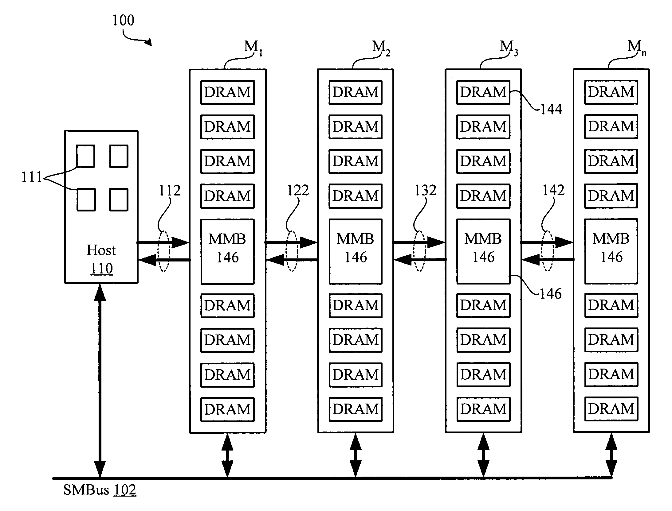
[0017]FIG. 3 is a block diagram illustrating some components of an example memory subsystem 100 utilizing DIMMs that may be used in conjunction with embodiments of the invention. It should be emphasized that embodiments of the invention are not limited only to memory subsystems that are implemented with DIMMs. For example, embodiments of the invention work equally well with memory subsystems that utilize single inline memory modules, or SIMMs. Thus, the generic term “memory module” is intended to include DIMMs, SIMMs, and other memory modules that include a plurality of memory devices. The number of memory modules in the memory subsystem may be more or less than the number illustrated in FIG. 3.

[0018] Referring to FIG. 3, the memory subsystem 100 includes a host 110, four memory modules M1, M2, M3, and M4, four memory channels 112, 122, 132, and 142, and a low-speed system management bus (SMBus) 160. The host 110 includes four counters 111, each counter corresponding to one of the ...


PUM


Abstract

Some embodiments of the invention accurately account for power dissipation in memory systems that include individual memory modules by keeping track of the number of read requests, the number of write requests, and the number of activate requests that are applied to the individual memory modules during selected time periods. If the sum of these totals exceeds a threshold level, the embodiments throttle the memory system, either by throttling the entire memory system based in response to the most active memory module, or by throttling individual memory modules as needed. Other embodiments of the invention may assign the same or different weights to activate requests, read requests, and write requests. Other embodiments are described and claimed.

Description

BACKGROUND OF THE INVENTION [0001] Digital processors, such as microprocessors, use a memory subsystem to store data and processor instructions. Some processors communicate directly with memory, and others use a dedicated controller chip, often part of a “chipset,” to communicate with memory. [0002] Conventional memory subsystems are often implemented using memory modules. Referring to FIG. 1, which illustrates an example conventional memory subsystem, a microprocessor 20 communicates with a memory controller / hub (MCH) 30 that couples the microprocessor 20 to various peripherals. One of these peripherals is system memory, shown as dual in-line memory modules (DIMMs) 40, 42, and 44 inserted in card slots 50, 52, and 54. In this example, each of the DIMMs 40, 42, 44 includes a number of memory devices 35, which may be DRAM memory devices. When connected, the DIMMs are addressed from MCH 30 whenever MCH 30 asserts appropriate signals on an Address / Control Bus 60. Data transfers between...

Claims


Application Information

Patent Timeline
IPC IPC(8): G06F1/20G06F12/00G06F13/16G11C5/00G11C5/14G11C7/04
CPCG06F1/206G06F13/161G11C7/04G11C5/14G11C5/143G11C5/00
Inventor MORROW, WARREN R.DAHLEN, ERIC J.NAYYAR, RAMANDHARANIPATHI, JAYAMOHANDAVID, HOWARD
Owner INTEL CORP
Why Eureka
Try Eureka