Axle with removable spindle and cam key

a technology of cam key and axle, which is applied in the direction of wheel-axle combination, coupling, rod connection, etc., can solve the problems of accelerating the deterioration of the spindle and its connection to the axle, the need to remove the spindle, etc., to facilitate facilitate the accurate and secure mounting of the spindle, and facilitate the effect of the removal of the spindl

Inactive Publication Date: 2006-01-05
DEXTER MARINE PROD OF GEORGIA LLC
View PDF8 Cites 24 Cited by
  • Summary
  • Abstract
  • Description
  • Claims
  • Application Information

AI Technical Summary

Benefits of technology

[0009] A feature of the invention is the cooperative relationship between the cam key, key hole and cam slot. The cam slot of the spindle is shaped with opposed, oppositely sloped bearing surfaces that receive the cam key. The cam key includes cam means for alternately engaging the bearing surfaces of the cam slot for urging the spindle in one direction along the axle when engaging one of the bearing surfaces and for urging the spindle in the opposed direction when engaging the other bearing surface. In the embodiment described herein, the cam means of the cam key is a sloped surface for wedge engagement with the bearing surfaces of the cam slot of the spindle. When the cam key is oriented in one position within the keyhole and in the cam slot of the spindle, the cam surface engages one of the bearing surfaces of the spindle. When the cam key is thrust into the keyhole the cam surface applies a force to the bearing surface of the spindle, and a component of the applied force urges the spindle axially along the axle. When the cam key is reversed or otherwise reoriented in the keyhole, its bearing surface engages the opposed bearing surface of the spindle and urges the spindle in the opposite direction along the axle. Thus, by orienting the cam key in one direction, the spindle is urged into a firm, static connection with respect to the axle, and by reorienting the cam key to engage the opposing bearing surface of the spindle, the cam key urges the spindle out of the axle. This provides the worker with the ability to expediently and securely mount the spindle in the end of the axle, not only locking the spindle to the axle but also using the cam means to wedge the spindle into its deepest seating within the axle. Further, when the spindle must be removed from the axle, the worker can extract the key from its keyhole in the axle, reorient the key, and then apply the key back through the key hole to the spindle, thus applying a wedging force against the bearing surface of the spindle that urges the spindle out of the axle.
[0010] Another feature of the invention is that the cam key includes a threaded shank that protrudes from the key hole that is exposed for mounting a threaded nut to the cam key, thereby assuring that the cam key is maintained in the key hole and continuously applies the desired wedge force against the spindle, for retaining the spindle in its desired position for wheel support.
[0014] Another object of this invention is to provide an axle assembly for a wheeled vehicle that facilitates accurate and secure mounting of a spindle to an axle, and facilitates the removal of the spindle from the axle.
[0015] Another object of this invention is to provide an axle assembly for a wheeled vehicle that is of simple and economic construction and assembly.

Problems solved by technology

While the above described axle assemblies usually are structurally sound and safe, there are occasions when the spindle must be removed from the axle due to wear, change in size, or accident, etc.
The salt and dampness from the water tends to accelerate the deterioration of the spindle and its connection to the axle.

Method used


Image

  • Axle with removable spindle and cam key
  • Axle with removable spindle and cam key
  • Axle with removable spindle and cam key

Examples


Embodiment Construction

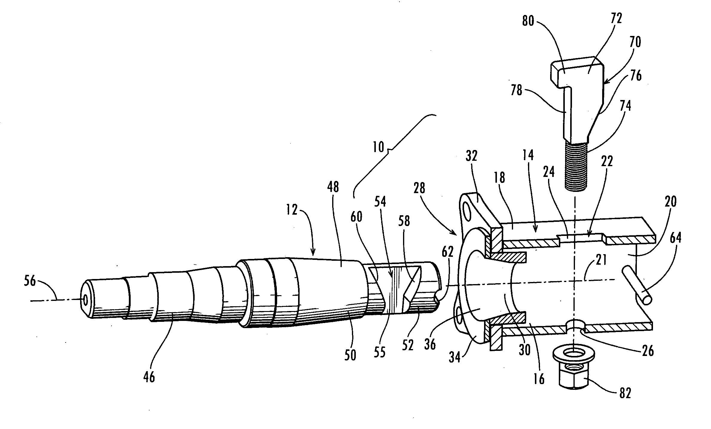
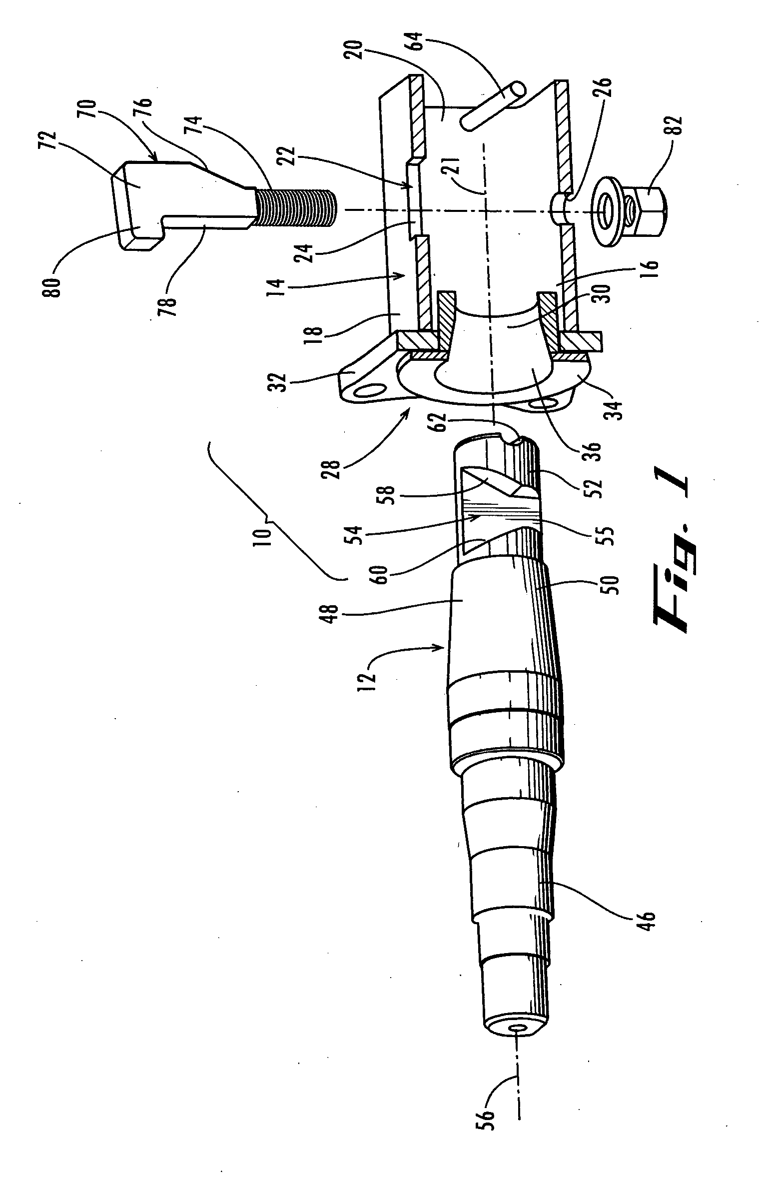
[0025] Referring now in more detail to the drawings, in which like numerals indicate like parts throughout the several views, FIG. 1 shows, in an expanded relationship, an axle assembly 10, showing only one end of axle 14 and the spindle that is received in the axle. A spindle 12 is mounted in the hollow end of an axle 14.

[0026] The axle is of tubular configuration, square in cross-section, having hollow ends, usually hollow along its entire length from side to side of a vehicle (the vehicle is not shown). For purposes of description of the invention, only one end of the axle 14 is illustrated.

[0027] Axle 14 includes opposed bottom and top walls 16 and 18 and opposed sidewalls 20 (only one shown). A keyhole 22 is formed through the top and bottom walls 16 and 18. The entrance opening 24 of the keyhole is formed in top wall 18, and the entrance opening is rectangular in shape. The guide opening 26 is formed in bottom wall 16 and is in alignment with the entrance opening 24.

[0028] ...


PUM


Abstract

An axle assembly includes a spindle (12) that extends through a mounting collar (28) into the open end of the axle. A cam key (70) moves through a key hole (22) in the axle and registers with the cam slot (54) of the spindle. The cam surface (76) of the cam key (70) is reversible with the cam surface (76) engaging either the bearing surface (58) or the bearing surface (60) of the spindle, to urge the spindle into or out of the axle.

Description

FIELD OF THE INVENTION [0001] This invention concerns an axle for a wheel of a vehicle. More particularly, the invention concerns an axle assembly whereby the spindle on which the wheel is mounted can be expediently and accurately mounted to the axle and expediently removed from the axle. BACKGROUND OF THE INVENTION [0002] The spindle that mounts a wheel to an axle assembly must be very accurately and rigidly connected to the axle assembly to assure proper operation and safety of the vehicle. For spring mounted axles the axle assembly will include an axle that extends transverse to the longitudinal center line of the vehicle and is supported by a spring system to the frame of the vehicle, and a mounting collar rigidly connected, as by welding, to the outwardly facing ends of the axle. One end of the spindle is inserted through the collar into the axle while the outer wheel support end of the spindle protrudes from the collar and is available for mounting the wheel. Various connector...

Claims


Application Information

Patent Timeline
Patent Type & Authority Applications(United States)
IPC IPC(8): B60B35/00
CPCB60B35/02B60B35/16B60B2310/305B60B2380/18B60B2900/541F16D1/097B60G2206/50B60Y2200/147F16B3/00F16B7/042F16D1/0894B60G2204/4404
Inventor MACKARVICH, CHARLES J.
Owner DEXTER MARINE PROD OF GEORGIA LLC
Why Eureka
Try Eureka