Dispensing systems, software, and related methods

a technology of material dispensing and software, applied in the field of material dispensing, can solve problems such as inconsistent synthetic yields

Inactive Publication Date: 2006-01-05
IRM
View PDF15 Cites 105 Cited by
  • Summary
  • Abstract
  • Description
  • Claims
  • Application Information

AI Technical Summary

Benefits of technology

[0019] The dispensing system optionally includes at least one positioning component operably connected to the controller. The positioning component is configured to moveably position one or more conduits and/or one or more fluidic material sites relative to one another. To illustrate, the positioning component optionally comprises at least one X/Y-axis linear motion component operably connected to at least one control drive that controls movement of the X/Y-axis linear motion component along an X-axis and a Y-axis of the dispensing system. In these embodiments, the controller is typically operably connected to the pressure source and is configured to simultaneously effect application of pressure in the conduits from the pressure source and moveably position the conduits and/or the fluidic material sites relative to one another such that volumes of fluid are conveyed from the conduits synchronous with the relative movement of the conduits and/or the fluidic material sites. In certain embodiments, the positioning component comprises at least one Z-axis linear motion component comprising at least one conduit support head that is configured to support at least segments of the conduits and that moves along a Z-axis of the dispensing system. The positioning component optionally comprises at least one object holder that is structured to support at least one fluidic material site. In some embodiments, at least one cleaning component is operably connected to the controller. The cleaning component is configured to clean at least segments of the conduits when the conduits are operably connected to the positioning component and the positioning component moves the conduit segments at least proximal to the cleaning component. For example, the cleaning component optionally comprises at least one vacuum chamber comprising at least one orifice into or proximal to which the positioning component moves the conduit segments such that an applied vacuum removes adherent material from at least external surfaces of the conduit segments.
[0020] In some embodiments...

Problems solved by technology

Density variations among volumes of dispensed fluids can lead to biased assay results and to inconsistent sy...

Method used


Image

  • Dispensing systems, software, and related methods
  • Dispensing systems, software, and related methods
  • Dispensing systems, software, and related methods

Examples


Embodiment Construction

I. Introduction

[0045] While the present invention will be described with reference to a few specific embodiments, the description is illustrative of the invention and is not to be construed as limiting the invention. Various modifications can be made to the embodiments of the invention described herein by those skilled in the art without departing from the true scope of the invention as defined by the appended claims. It is also noted here that for a better understanding, certain like components are designated by like reference letters and / or numerals throughout the various figures. Further, unless defined otherwise, all technical and scientific terms used herein have the same meaning as commonly understood by one of ordinary skill in the art to which the invention pertains. Certain terms defined herein, and grammatical variants thereof, are more fully defined by reference to the specification in its entirety.

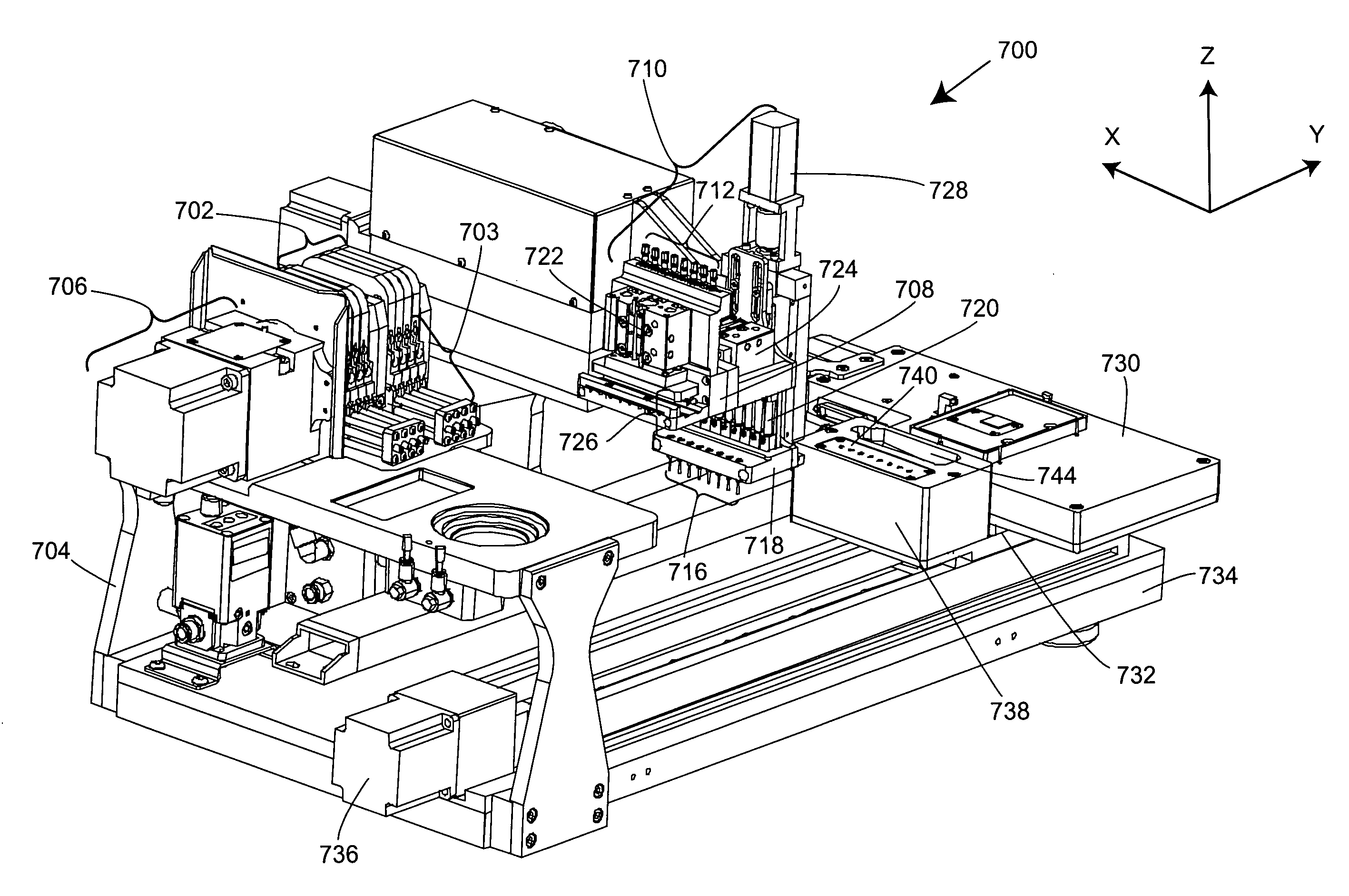
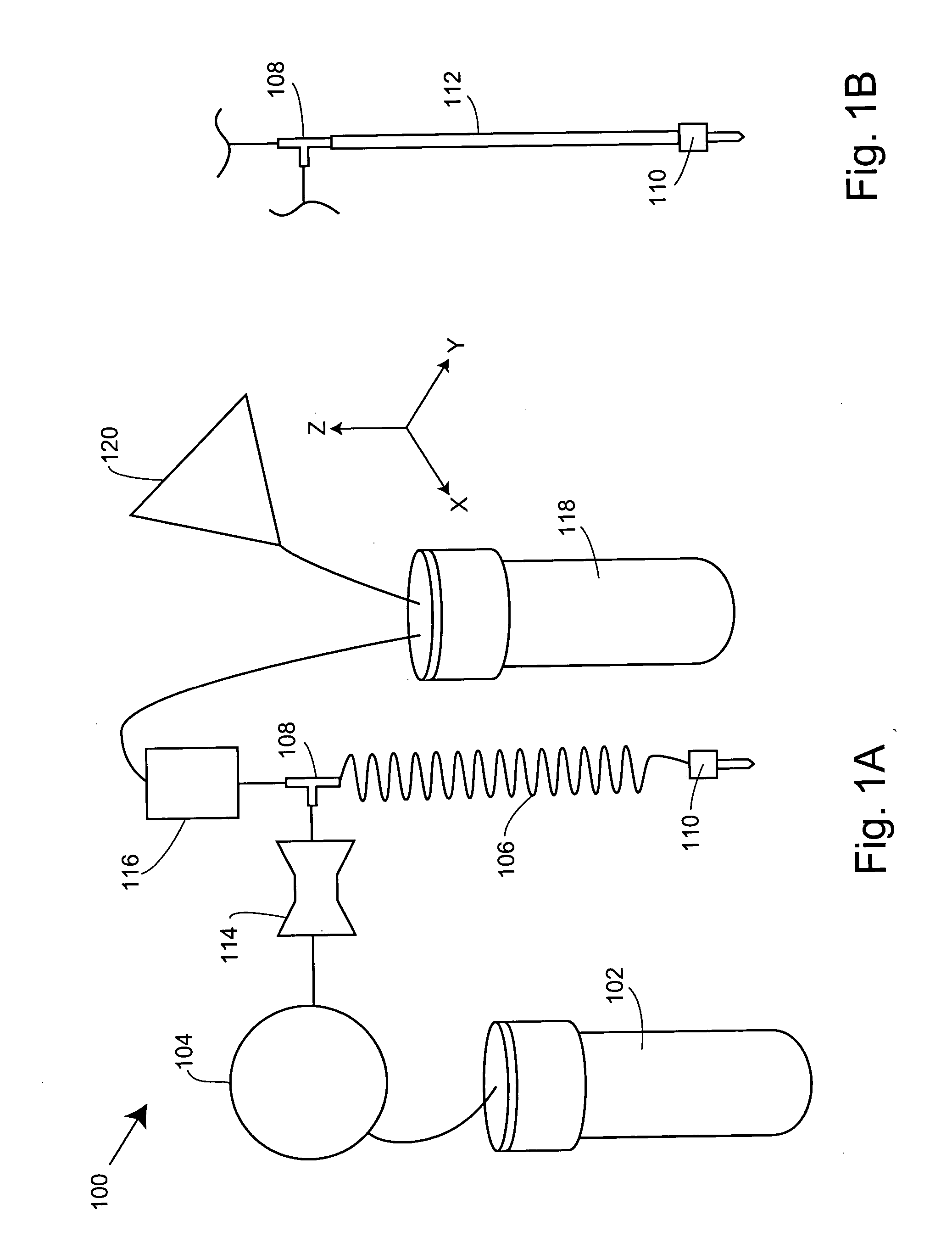
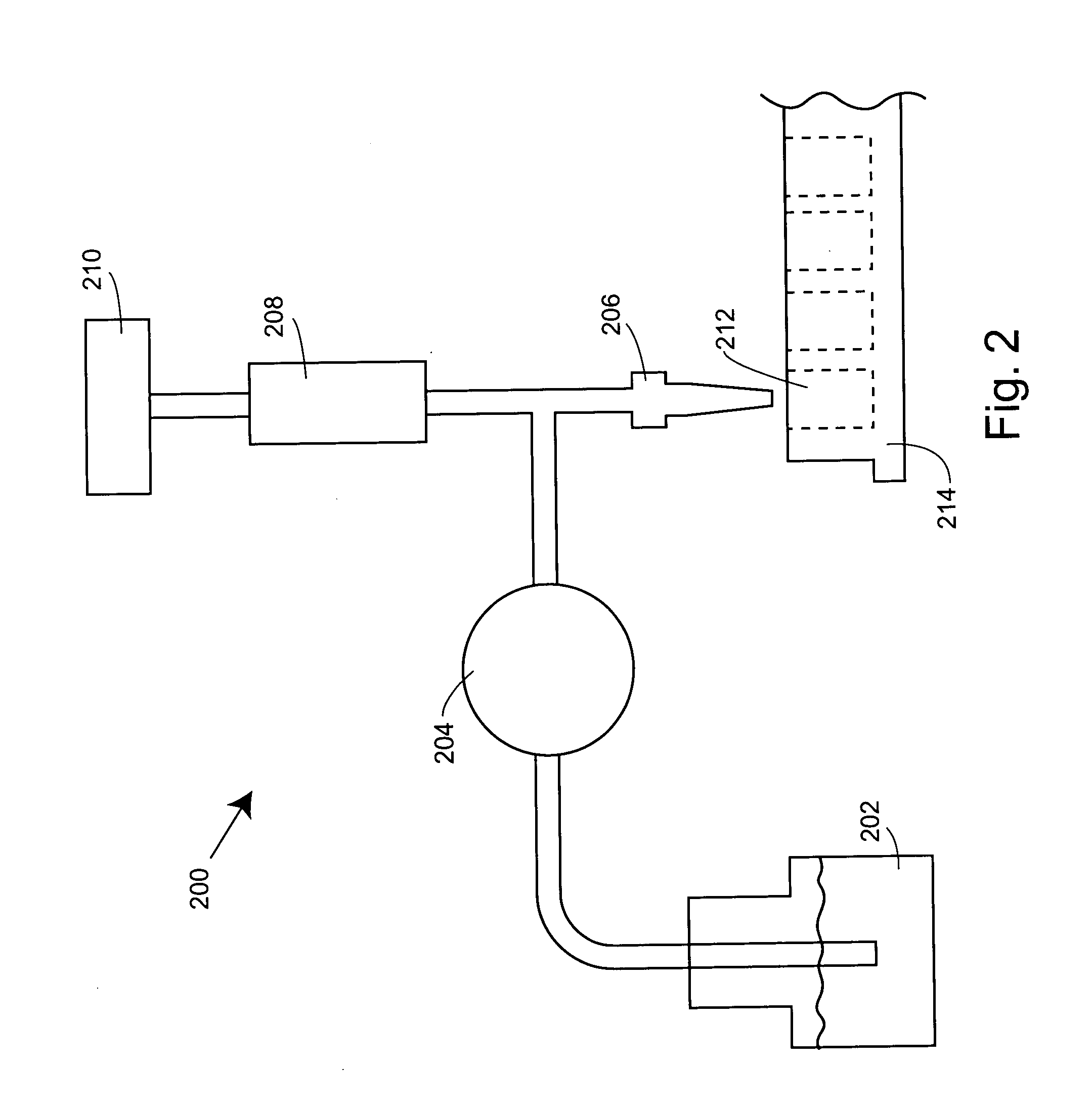
[0046] The present invention relates to accurate and efficient fluidic ma...


PUM


Abstract

The present invention provides dispensing systems that include peristaltic pumps and other pressure sources for the efficient delivery of accurate volumes of fluidic materials into the wells of multi-well containers or onto substrate surfaces. These systems are typically configured to dispense volumes of fluid having substantially uniform densities. Related computer program products and methods of dispensing fluidic materials are also provided.

Description

CROSS-REFERENCES TO RELATED APPLICATIONS [0001] This application claims the benefit of U.S. Provisional Application No. 60 / 577,849, filed Jun. 7, 2004, the disclosure of which is incorporated by reference in its entirety for all purposes.FIELD OF THE INVENTION [0002] The present invention relates generally to material dispensing. In addition to dispensing systems, related software and methods for efficiently and accurately dispensing selected quantities of materials are provided. BACKGROUND OF THE INVENTION [0003] High-throughput screening devices and systems are important analytical tools in the process of discovering and developing new drugs. Drug discovery procedures typically involve synthesis and screening of candidate drug compounds against selected targets. Candidate drug compounds are molecules with the potential to modulate diseases by affecting given targets. Targets are typically biological molecules, including proteins such as enzymes and receptors, or nucleic acids, whi...

Claims


Application Information

Patent Timeline
IPC IPC(8): B01L3/02G01N35/08G01N35/10
CPCB01J2219/00315G01N35/1065B01J2219/00355B01J2219/0036B01J2219/00364B01J2219/00389B01J2219/004B01J2219/00418B01J2219/00466B01J2219/005B01J2219/00527B01J2219/00691B01J2219/00695B01J2219/00704B01J2219/0072B01J2219/0074B01J2219/00743B01L3/021B01L3/0241B01L3/0293B01L9/52B01L9/523B01L2200/025B01L2200/0605B01L2300/0829B01L2400/0481B01L2400/0487B01L2400/0655G01N35/08G01N35/1002G01N35/1016B01J2219/00353B01L13/02
Inventor CHANG, JIM YUCHENMICKLASH, KENNETH J. IIDOWNS, ROBERT CHARLESMAINQUIST, JAMES KEVINSHAW, CHRISTOPHER M.
Owner IRM
Why Eureka
Try Eureka