
Digital manufacturing of removable oral appliances

a technology of oral appliance and digital manufacturing, applied in the field of dental appliances, can solve the problems of increasing trimming requirements, requiring less time and skill, etc., and achieve the effects of enhancing design, reducing trimming time, and improving design uniformity and final shap

Inactive Publication Date: 2006-01-05
GREAT LAKES ORTHODONTICS
View PDF25 Cites 109 Cited by
  • Summary
  • Abstract
  • Description
  • Claims
  • Application Information

AI Technical Summary

Benefits of technology

[0007] This invention provides pc-based methods for designing and trimming the body of removable dental appliances. Appliance design is performed in a computer, and computer-controlled machines are used to mill the body of the appliance. The advantages include improved uniformity of design and final shape, reduced trimming time, integration with digital diagnostic information to enhance design, and ability to provide digitally-based design input from the prescribing doctor.
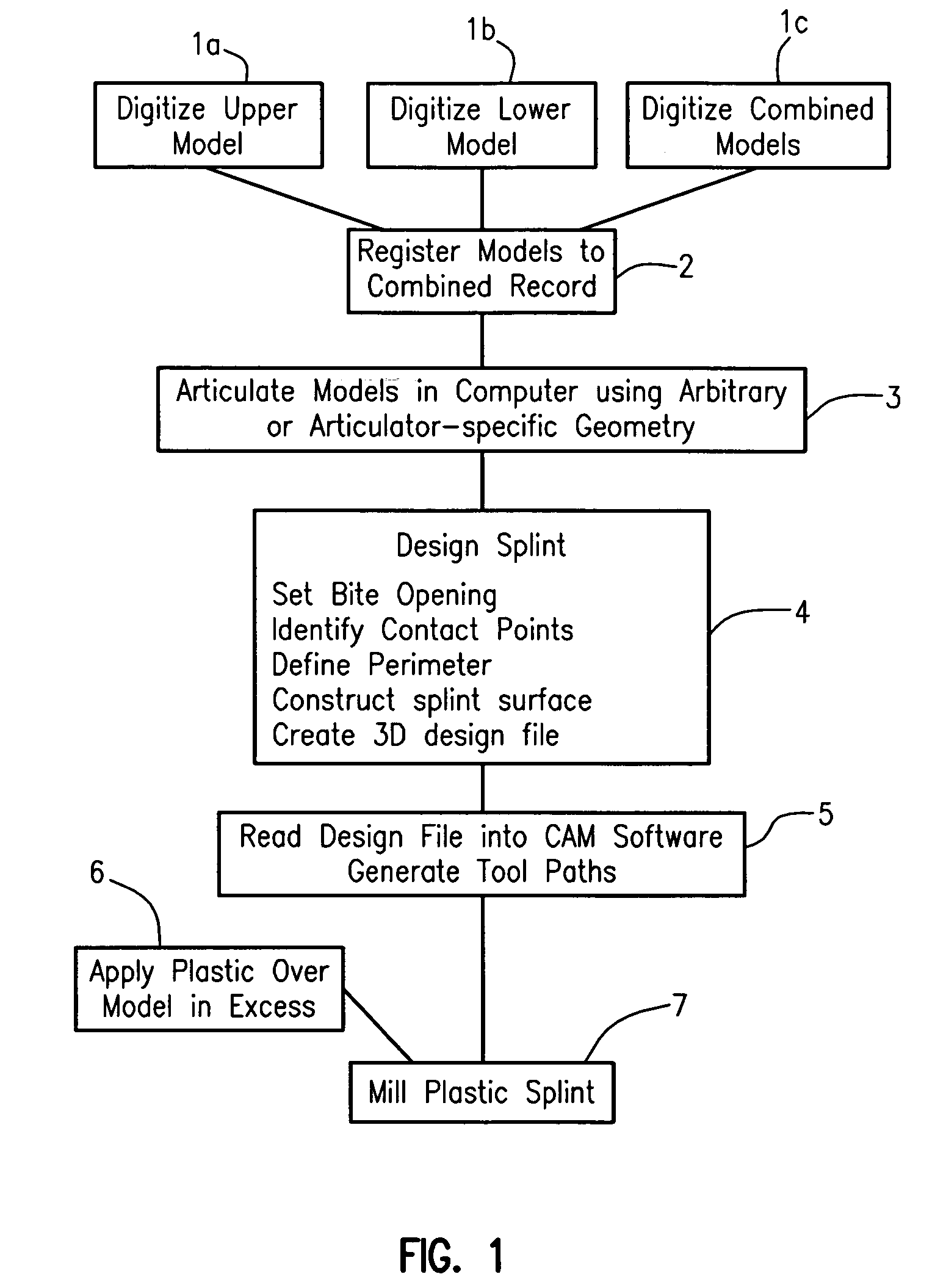
[0031] Turning finally to appliance production, the specific type of plastic for a removable appliance is adapted to a plaster model in excess which is milled away to produce the desired appliance surface. Standard CAM software may be used to convert the design file into the required tool paths to mill excess plastic and produce the desired surface. Since the plastic is already adapted to the complex anatomy of the teeth, detailed dental anatomy does not have to be milled. This greatly reduces the size of the design file and the complexity of the geometry to be machined. Typically, a multi-axis machine center is used to mill the appliance. A three axis system may be capable of producing the majority of cases, while a four or five axis system is required to produce undercut regions.

Problems solved by technology

Applying extra plastic to a model requires less time and skill than minimizing excess, thereby increasing trimming requirements.

Method used


Image

  • Digital manufacturing of removable oral appliances
  • Digital manufacturing of removable oral appliances
  • Digital manufacturing of removable oral appliances

Examples


Embodiment Construction

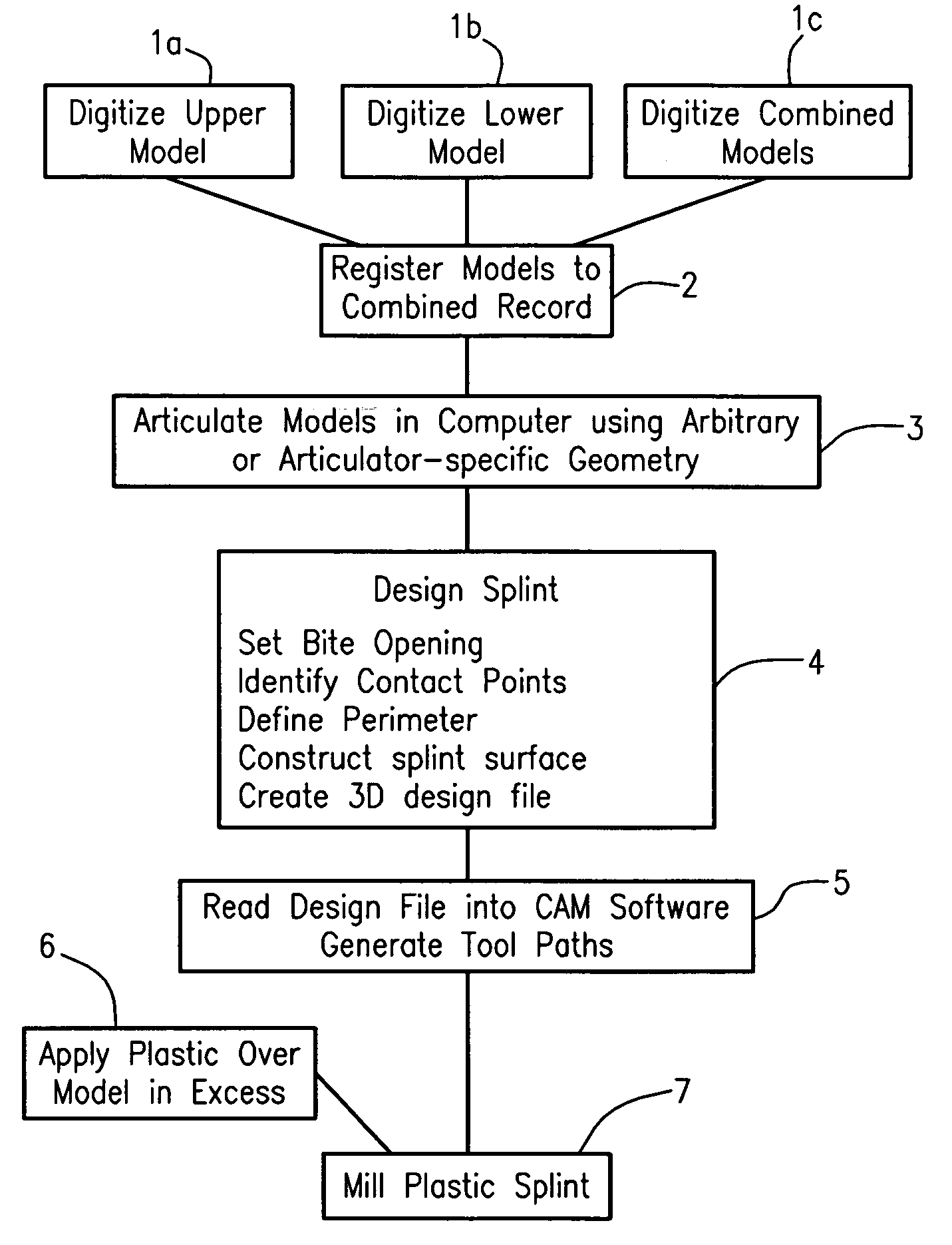
[0039] While the basic method described in the foregoing Summary of is applicable to a variety of removable appliance types, details of modeling the dentition, appliance design, and appliance production are described using an occlusal splint as an example. The process for producing an occlusal splint is summarized in FIG. 1. Digital 3D files of the upper, lower and combined models are designated 1a, 1b and 1c in FIG. 1. Registration of the individual upper 1a and lower 1b models to the combination scan 1c is represented at 2. The first step in appliance design, articulation, is shown at 3, and the design process is shown at 4. Appliance production includes generating tool paths 5, applying plastic 6 and milling 7.

[0040] Turning first to modeling the dentition, several methods are known in the art for creating a 3D representation of dental anatomy in a computer with sufficient detail to carry out this invention. A preferred method for obtaining a 3D representation of (digitizing) a ...


PUM


Abstract

A digitally-based method is described for the design and production of customized removable dental appliances. The plastic component of custom appliances is designed using software, and milled directly over a plaster model of the dentition. A patient's upper, lower, and bite-registered arches are digitized, registered to a bite or centric occlusion position, and articulated in software using either an average geometry or the geometry of a specific articulator. Appliance design is performed by defining the desired plastic surfaces and margins as dictated by the relative movement and positions of the arches as functionally required for a specific appliance. Standard CAM software is used to read the design file and command a multiaxis machine center to mill the plastic while directly on a plaster model.

Description

CROSS REFERENCE TO A RELATED APPLICATION [0001] Applicants claim priority based on provisional application No. 60 / 573,690 filed May 24, 2004 and entitled “Digital Manufacturing Of Oral Appliances” which is incorporated herein by reference.BACKGROUND OF THE INVENTION [0002] This invention relates to the art of dental appliances, and more particularly to a new and improved method of making removable dental appliances. [0003] Dental appliances make up a diverse group of devices ranging from ceramic orthodontic brackets to soft mouth guards. Some are custom-fitted devices and some are supplied generically to fit a variety of patients. A distinct subgroup of custom-fitted appliances consists of appliances that are removable from the mouth. As a group, removable appliances include orthodontic retainers, occlusal splints, palatal expanders, Herbst appliances, and appliances to relieve sleep apnea. They are produced in commercial dental laboratories as well as in office dental laboratories....

Claims


Application Information

Patent Timeline
Patent Type & Authority Applications(United States)
IPC IPC(8): A61C5/00A61C3/00A61C7/00
CPCA61C5/007A61C13/0004A61C7/002A61C7/00G16H20/40
Inventor LAUREN, MARK D.KUNKEMOELLER, JAMES R.
Owner GREAT LAKES ORTHODONTICS
Learn More