Gaming machine with action unit container

Inactive Publication Date: 2006-01-05
ATLANTIC CITY COIN & SLOT SERVICE
View PDF5 Cites 6 Cited by
  • Summary
  • Abstract
  • Description
  • Claims
  • Application Information

AI Technical Summary

Benefits of technology

[0031] the ability to convey a random game outcome by selectively trapping movable objects in receptacle elements;
[0032] provide an enhanced degree of anticipation by the player by allowing movable objects to pass through the various receptacle elements repeatedly before finally trapping a movable object in a specified receptacle element to convey the game ou

Problems solved by technology

Many players are reluctant to try completely new games because they must spend time to learn the new game.
However, before the present invention, the Keno display device has been unsuitable for use with gaming devices.
One of the reasons this is so is because Keno is susceptible to environmental influences.
As the balls are jumbled in the Keno ball device, static electricity, dust, and contaminants build up on the balls.
This may cause the balls to stick to each other or to components in the display device thereby influencing the randomness of the game.
Another reason the game of Keno has been unsuitable as an indicator for a gaming device is that it requires a great deal of human involvement.
Not only does this require excessive human involvement for an automated gaming device (the greater the human involvement, the greater the cost of operating the game), the game is also susceptible to tampering and cheating.
Because of their susceptibility to environmental influences and tampering and their dependence on human operators and maintenance personnel, Keno games are not allowed in at least one major gaming jurisdiction.
Furthermore, these disadvantages have prevented Keno display devices and other devices that use jumbled balls from being modified for use with gaming devi

Method used


Image

  • Gaming machine with action unit container
  • Gaming machine with action unit container
  • Gaming machine with action unit container

Examples


Embodiment Construction

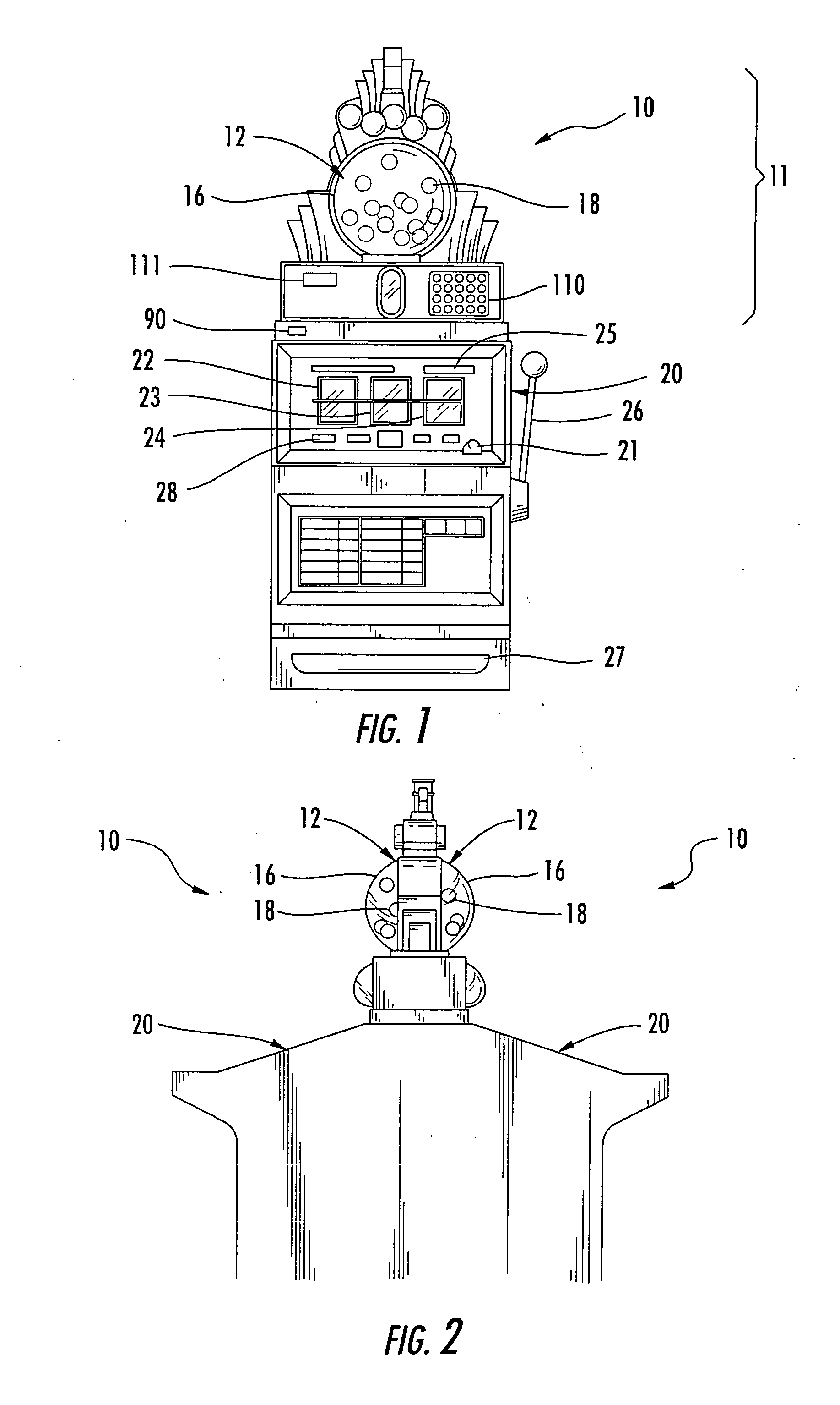
[0057] As seen in FIG. 1, one embodiment disclosed herein comprises a gaming device, generally indicated by reference number 10. Gaming device 10 comprises a display device 11 and a game apparatus 20. Display device 11 may comprise a jumbled ball display 12.

[0058] Game Apparatus

[0059] With continuing reference to FIG. 1, game apparatus 20 may be any of a large number of devices that are configured to allow players to play a game. For example, game apparatus 20 may utilize reel displays, such as spinning reels 22-24 or a video display (not shown), to display outcomes of the game. Various devices may also be provided for accepting value from a player, such as a coin slot 21 or card reader 25, and for awarding prizes, such as a coin dispenser 27. A handle 26 and button 28 are provided for activating game apparatus 20 to begin a game. In at least one embodiment, game apparatus 20 may be an S2000™ or S Plus™ model gaming device manufactured by International Game Technology in Reno, Nev...


PUM


Abstract

A gaming device including a game apparatus enabling a player to play the game, the gaming device having: a container with at least one movable object located within; one or more receptacle elements capable of receiving the movable objects, where the receptacle element includes a barrier member that allows movement of the movable objects through the receptacle element when the barrier member is in a first position and that constrains the movable object when the barrier member is moved to a second position; and a controller in communication with the barrier member and the game apparatus, is disclosed. The controller is designed to determine a game outcome and communicate the result to the player by activating the barrier member of the receptacle element to move from an open position to a closed position, thus displaying the result to the player by trapping the movable object in the receptacle element corresponding to the game outcome. Typically, the receptacle element will bear at least one game-related symbol or image corresponding to the prize to be awarded. In addition, a method of playing a game involving placing a wager using the aforementioned gaming device is disclosed.

Description

CROSS REFERENCES TO RELATED APPLICATIONS [0001] This application is a continuation-in-part application of U.S. patent application Ser. No. 10 / 937,018, filed on Sep. 19, 2004; this application is also a continuation-in-part application of U.S. patent application Ser. No. 10 / 883,489, filed on Jun. 30, 2004. The above referenced applications are hereby expressly incorporated by reference in their entireties.BACKGROUND OF THE INVENTION [0002] The present invention relates to a display device for use with a gaming device that may select one or more movable objects to convey a game outcome. [0003] Gaming Devices [0004] Gaming devices are well known in the art and a large variety of gaming devices have been developed. In general, gaming devices allow users or players to play a game. In many casino-type gaming devices, the outcome of the game depends, at least in part, on a randomly generated event. For example, a gaming device may use a random number generator to generate a random or pseud...

Claims


Application Information

Patent Timeline
IPC IPC(8): A63F13/00
CPCG07F17/3211G07F17/3202
Inventor SEELIG, JERALD C.HENSHAW, LAWRENCE M.
Owner ATLANTIC CITY COIN & SLOT SERVICE
Why Eureka
Try Eureka