
Process and device for controlling the robotal device

Inactive Publication Date: 2006-01-05
KUKA ROBOTER
View PDF5 Cites 18 Cited by
  • Summary
  • Abstract
  • Description
  • Claims
  • Application Information

AI Technical Summary

Benefits of technology

[0050] The basic object of the present invention is to improve a process and a device of the type mentioned in the introduction, while avoiding the problems mentioned, such that compatibility can be achieved if needed, i.e., especially in case of the use of the control with a new kinemati

Problems solved by technology

Determination of forces, torques and kinetic energy; no time-optimal motion programming and no related model based control is possible without such procedures.
However, such methods are usually used outside the robot control (cf.
A fundamental restriction arises during the implementation for mathematical reasons: It is not possible to specify a general mathematical process for determining all procedures 1 through 5 from a given geometric and dynamic description of a robot.
Thus, no analytical solution of the backward calculation is possible for any desired oblique positions of axes and for any desired distance between axes.
In addition, the effort needed for the calculation also increases greatly for the analytical solution—if any such solution exists—in case of the use of the most modern methods (Kovacs, elsewhere).
As in the case of the backward calculation of kinematics with open chain, there is no general solution in case of closed kinematic chains.
The fact that all procedures 1 through 5 must be implemented for each kinematic, so that the scope of the control also grows with the number of the kinematics to be supported at will, besides the effort needed for the development and care, is to be considered to be disadvantageous here, in particular.
What is to be considered to be disadvantageous in this procedure is, in particular, the fact that it is not possible to implement the procedures 1 through 5 in a generally valid form, and especially the lack of ambiguity of the solution, as well as the convergence characteristic, which is critical for real-time applications, and the often insufficient accuracy argue against the numerical methods, which are used by necessity.
However, this is not possible in case of the processes and the devices of the type mentioned in the introduction, because the manufacturer of the control would conversely have to disclose detail information concerning the control to the manufacturer of the kinematics.

Method used


Image

  • Process and device for controlling the robotal device
  • Process and device for controlling the robotal device
  • Process and device for controlling the robotal device

Examples


Embodiment Construction

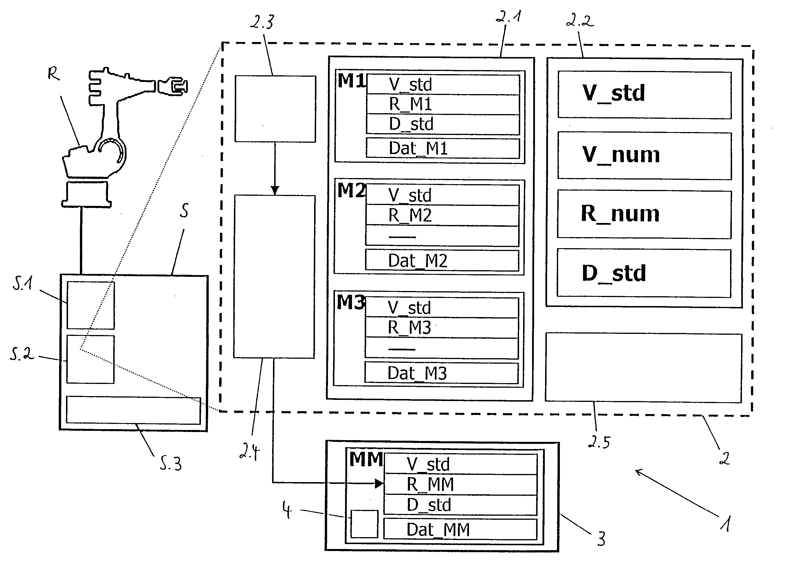
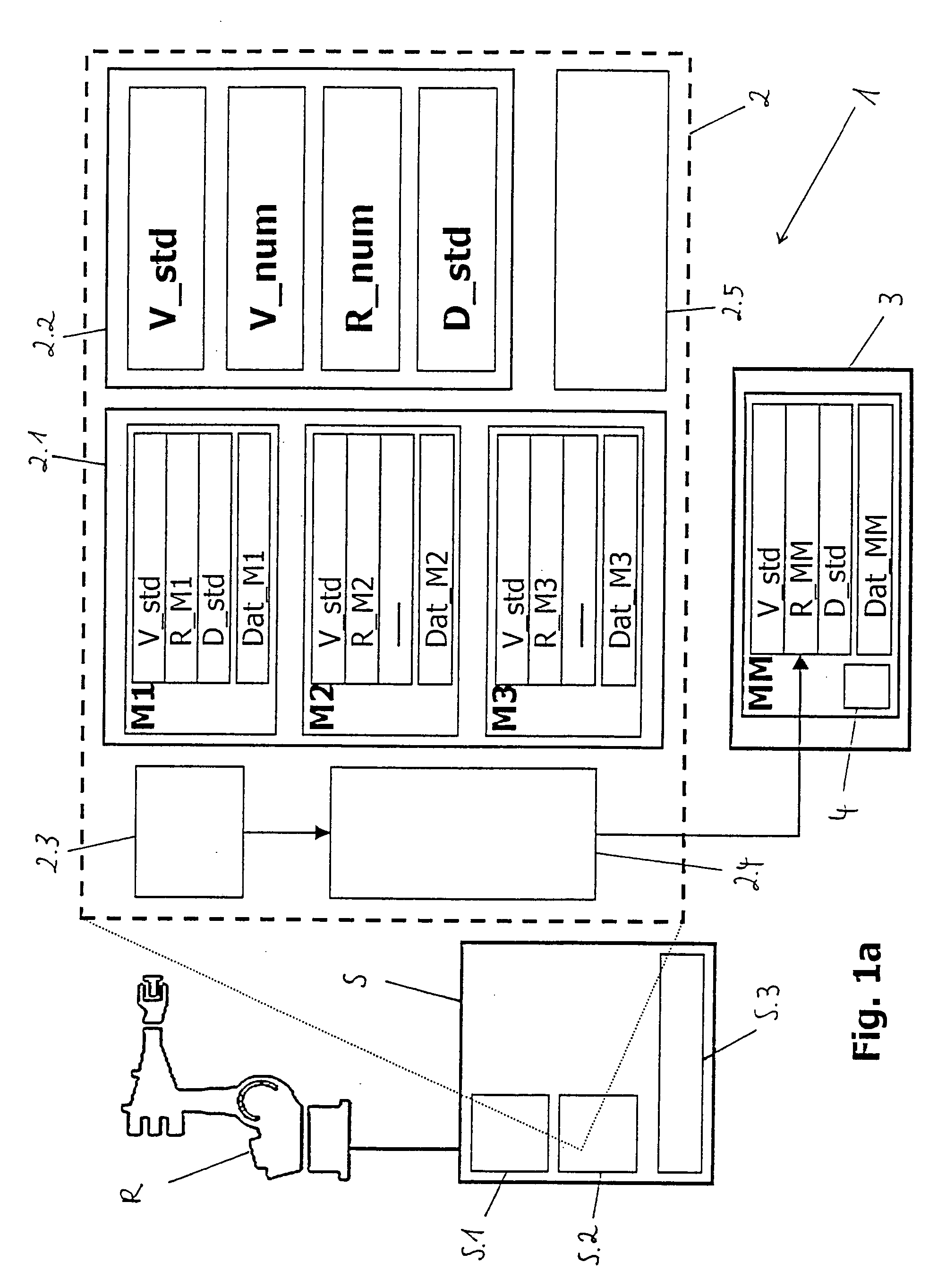
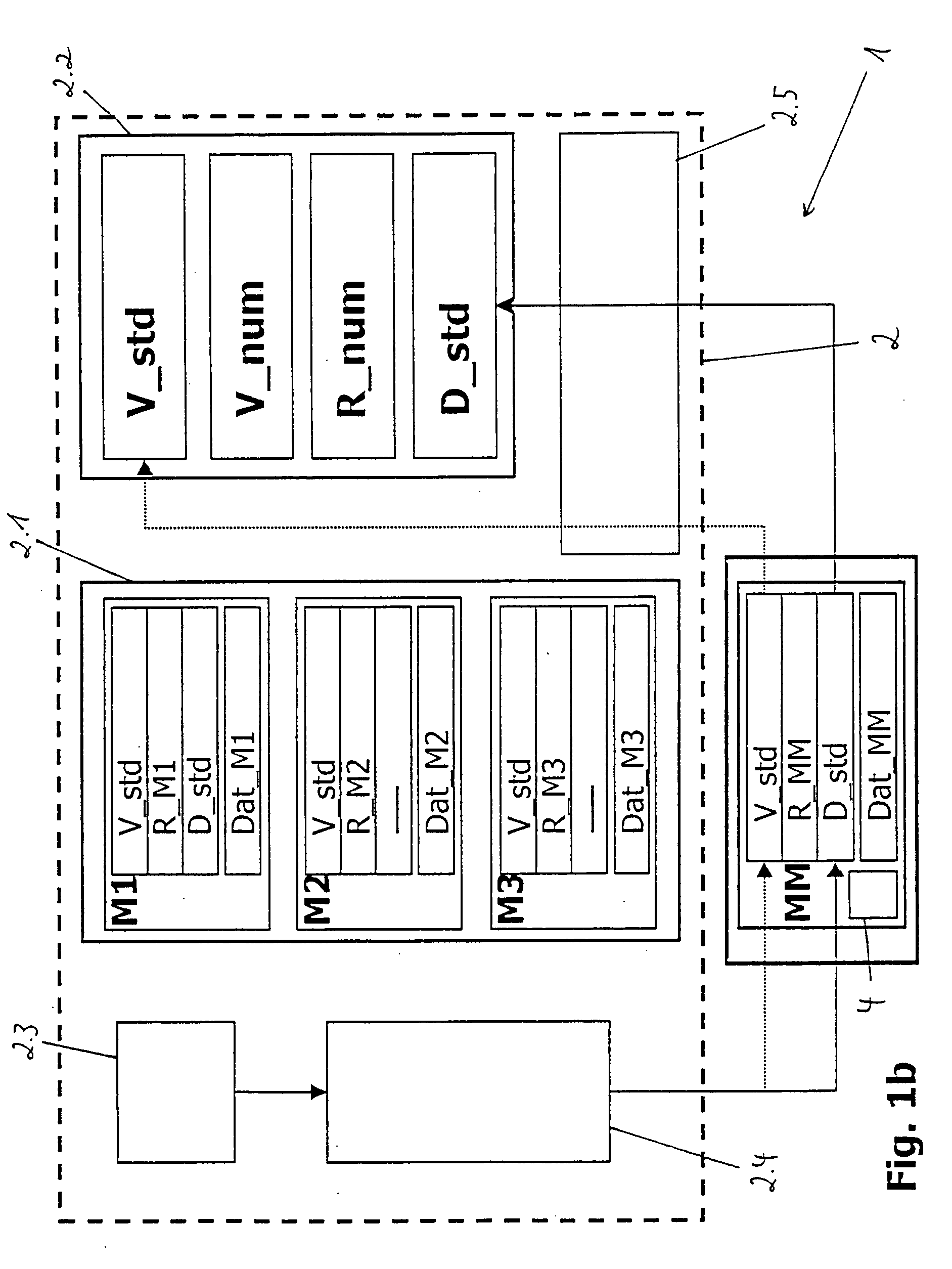
[0064] Referring to the drawings in particular, FIG. 1a shows a typical multiaxial industrial robot R along with the corresponding control unit or control means 5, in which a processor unit S.1, a working memory S.2 as well as a mass storage unit S.3 are also shown as components of such a control means 5, which are regularly present. Furthermore, FIG. 1a shows, on the basis of a block diagram, a device 1 according to the present invention for controlling a robotal device, such as the multiaxial industrial robot R, with a set of kinematic models M1-M3 in the core 2 of the robot control as well as with a model module MM with the backward calculation called.

[0065] First, the device 1 has a control core 2, which is preferably set up in a programmed form, i.e., on the basis of suitable software on a control computer (the control unit S.1) for the robotal device R. This regularly happens by loading a corresponding software application into the working memory S.2 of the control computer. ...


PUM


Abstract

A process is provided for controlling a robotal device, such as a multiaxial industrial robot, by a control unit, with a control core for executing control processes for the robotal device. An interface function checks whether models and / or procedures optionally contained in the control core or additional models and / or transformation procedures and / or special algorithms of kinematic structures, which can be preset at the interface are used as model modules for motion-relevant variables of the robotal device. Special and third-party kinematics can thus also be operated with a control device suitable for executing the process without the control itself having to be modified.

Description

CROSS REFERENCE TO RELATED APPLICATIONS [0001] This application claims the benefit of priority under 35 U.S.C. § 119 of German Application DE 10 2004 031 485.3 filed Jun. 30, 2004, the entire contents of which are incorporated herein by reference. FIELD OF THE INVENTION [0002] The present invention pertains to a process and a device for controlling a robotal device, such as a multiaxial industrial robot, by means of a control means with a control core for carrying out control processes for the robotal device. BACKGROUND OF THE INVENTION [0003] Programmable, computer-aided, i.e., program-based control devices are nowadays usually used for controlling automated robotal devices, such as multiaxial industrial robots, portal robots (robots arranged and movable in a portal frame), SCARA robots (Selective Compliance Assembly Robot Arm—a robot selectively compensating in one plane, pivoted arm robot) or palletizing robots. Procedures for transforming kinematic and dynamic variables and syst...

Claims


Application Information

Patent Timeline
IPC IPC(8): G06F19/00B25J9/16
CPCB25J9/1602G05B2219/34202B25J9/1656
Inventor WEISS, MARTIN
Owner KUKA ROBOTER
Learn More