Optical storage capable of reducing power consumption

a technology of optical storage and power consumption, applied in the field of optical storage capable, can solve the problems of increasing power consumption, strong turbulence, flow resistance, etc., and achieve the effects of reducing power consumption, reducing the integrated value of skin friction coefficient, and reducing flow resistan

Inactive Publication Date: 2006-01-05
SAMSUNG ELECTRO MECHANICS CO LTD
View PDF2 Cites 16 Cited by
  • Summary
  • Abstract
  • Description
  • Claims
  • Application Information

AI Technical Summary

Benefits of technology

[0023] The present invention has been made to solve the foregoing problems of the prior art and therefore one object of the present invention is to modify a disk-receiving space into a structure capable of decreasing flow resistance induced from turbulent motion in the high speed rotation of a disk in order to reduce the integrated value of skin friction coefficient on the surface of the disk, thereby reducing power consumption.

Problems solved by technology

The high-speed rotation of the disk causes various problems such as strong turbulence, flow resistance, friction and fluttering induced from the flow of fluid in a space around the disk.
These problems may also create vibration and noise thereby increasing power consumption.
This is particularly disadvantageous in case of a notebook computer since a battery of the notebook computer will be more rapidly exhausted thereby to reduce run time.
As shown in FIG. 1, the conventional OMS housing is spaced at predetermined distances from the top and underside of the disk, but does not provide any structure or configuration for improving the flow of fluid in the rotation of the disk.
This as a result generates vibration and noise to the disk as well as increases power consumption because of increase in flow resistance.
High-speed rotation of the disk inside the optical storage creates strong turbulent motion or turbulence, which in turn collides against the side wall of the housing 1 generating vibration and noise.
The flow of fluid around the disk sharply increases skin friction and torque at the circumference of the disk thereby elevating power consumption.
The sharp rise of the skin friction coefficient curve will have a large value when integrated, and therefore can increase power consumption since power consumption is proportional to the integrated value of a skin friction coefficient curve as will be described later.
As a drawback, the conventional optical storage consumes more power because of the above-described fluttering, turbulent fluctuation and increase in skin friction and torque around the circumference of the disk A solution to this problem was disclosed in Korean Patent Application No. 1998-13873, entitled “Apparatus for Reducing Noise in an Optical Disk Drive.” This document proposes grooves formed in the top of a tray, by which radial flow generated in the rotation of a disk is converted perpendicularly or toward the center of rotation of the disk.
However, this structure has only a limited capability for decreasing skin friction or torque induced from fluid flowing in a radial direction of the disk, and therefore can reduce power consumption by an insignificant quantity.
Furthermore, since this apparatus modifies only the tray 2 under the disk 10, but does not provide any means for preventing flow resistance occurring on the top or side of the disk 10 owing to fluid fluctuation.
Accordingly, this apparatus still has a problem in that it cannot obtain an effect of reducing skin friction, noise or vibration.
This apparatus also cannot fundamentally prevent fluttering induced from the pressure difference between above and under the disk in the high speed rotation of the disk and therefore the increase of flow resistance and skin friction.
This problem is equally observed not only the optical storage but also a Hard Disk Drive (HDD) which turns a disk at a high speed.

Method used


Image

  • Optical storage capable of reducing power consumption
  • Optical storage capable of reducing power consumption
  • Optical storage capable of reducing power consumption

Examples


Embodiment Construction

[0049] Preferred embodiments of the present invention will now be described in detail with reference to the accompanying drawings.

[0050]FIG. 4A is a cross-sectional view illustrating a cover of a housing according to the present invention, FIG. 4B illustrates a modification to the housing shown in FIG. 4A, FIG. 5A is a cross-sectional view illustrating a shroud of a housing according to the present invention, FIG. 5B illustrates a modification to the housing shown in FIG. 5A, and FIG. 6 is a cross-sectional view illustrating bumps mounted on a base of a housing according to the present invention.

[0051] First, the cover structures will be described with reference to FIGS. 4A and 4B.

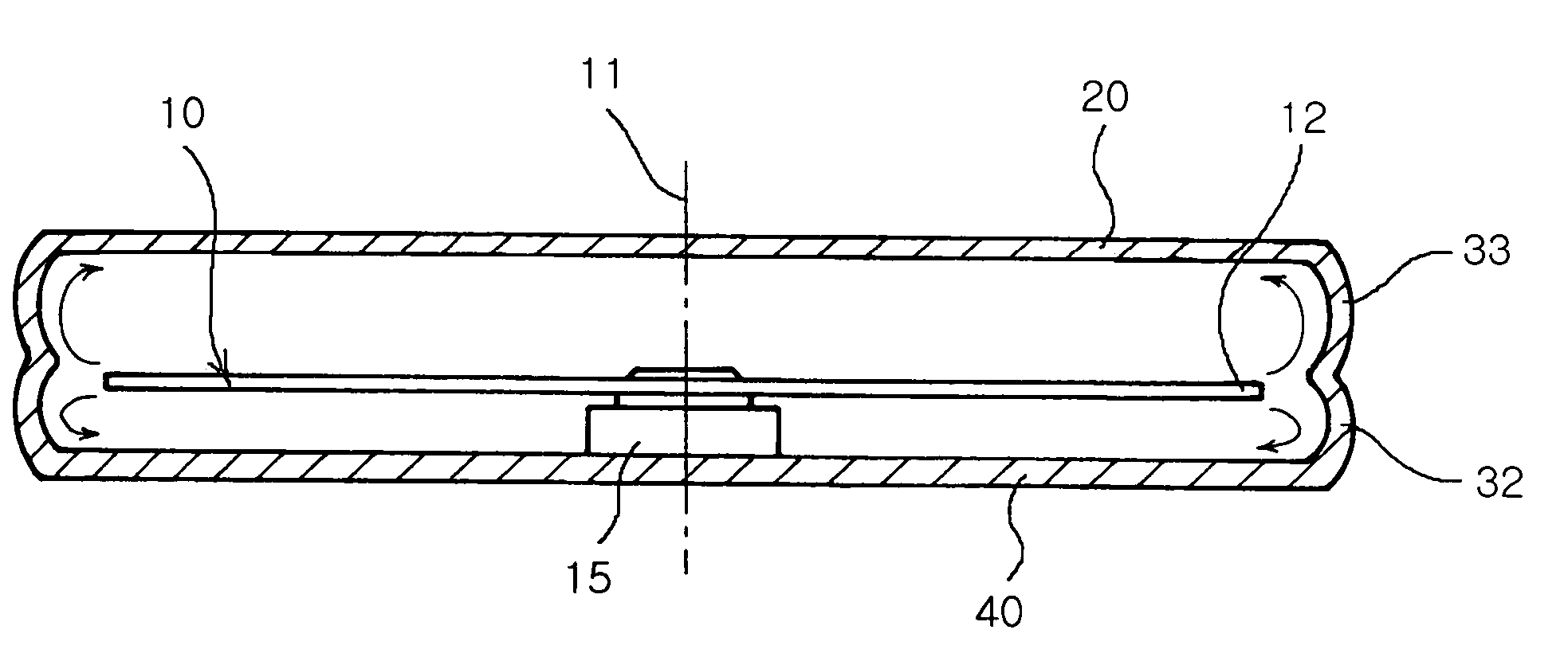
[0052] As shown in FIG. 4A, a disk 10 is received within a housing including a cover 20 as the top of the housing, a shroud 30 as the side wall of the housing and a base 40 as the bottom of the housing. A drive unit 15 is mounted on the base 40 to turn the disk 10 around a drive axis 11.

[0053] In the c...


PUM

PropertyMeasurementUnit
angleaaaaaaaaaa
angleaaaaaaaaaa
diametersaaaaaaaaaa

Abstract

The invention relates to an apparatus having a disk-receiving space designed into a structure capable of reducing skin friction, flow resistance and torque, which are generated on the surface of a disk and within a housing, thereby to reduce power consumption. The invention provides an optical storage, in which a base is defined in a bottom of a space which receives a disk. A drive unit is mounted on the base for turning the disk around a drive axis. A shroud is defined in a side of the space, and a cover is defined in a top of the space. The cover has a slanted line extended from a central portion of the cover toward the shroud at an upward inclination with respect to a disk plane when seen in a cross-section taken along a line perpendicular to the disk plane.

Description

CLAIM OF PRIORITY [0001] This application claims the benefit of Korean Patent Application No. 2004-50724 filed on Jun. 30, 2004, in the Korean Intellectual Property Office, the disclosure of which is incorporated herein by reference. BACKGROUND OF THE INVENTION [0002] 1. Field of the Invention [0003] The present invention relates to an optical storage capable of reducing power consumption. More particularly, the present invention designs a disk-receiving space into a structure capable of reducing skin friction, flow resistance and torque, which are generated on the surface of a disk and within a housing owing to the flow of fluid in vicinity of the disk in the high speed rotation of the disk, thereby to reduce power consumption, noise and vibration of an optical storage or a hard disk drive. [0004] 2. Description of the Related Art [0005] Optical storages are an apparatus for storing (recording) or regenerating (retrieving) voice, image and text data based upon optical laser technol...

Claims


Application Information

Patent Timeline
Patent Type & Authority Applications(United States)
IPC IPC(8): G11B33/14
CPCG11B33/148G11B33/1446G11B33/14
Inventor KIM, JOONG ELCHOI, JUN KUN
Owner SAMSUNG ELECTRO MECHANICS CO LTD
Why Eureka
Try Eureka