Misregistration when printing speed is changed, cutting misregistration, or pinter in which variation of printing density can be controlled

a printing machine and printing speed technology, applied in printing presses, rotary letterpress machines, printing presses, etc., can solve the problems of affecting the efficiency of rotary printing machines, and unable to keep up with the dispersion, so as to prevent the occurrence of broken, the effect of suppressing the fluctuation of cut registration

Inactive Publication Date: 2006-01-12
MITSUBISHI HEAVY IND LTD
View PDF0 Cites 36 Cited by
  • Summary
  • Abstract
  • Description
  • Claims
  • Application Information

AI Technical Summary

Benefits of technology

[0026] It is a second object of the invention to provide a cut-registration control technique of a printing machine for suppressing fluctuation in cut registration while changing print speed, thereby preventing the occurrence of broke due to the change of print speed.

Problems solved by technology

Such considerable misregistration occurs even though the phase control motor has adequate responsive performance in itself, because the automatic image-registration device 11 is feedback controlled according to a control time constant configured at a relatively large value due to the necessity of preventing hunting.
More specifically, when vertical image misregistration occurs during the acceleration, the images disperse vertically with one another at such high speed that the automatic image-registration device 11 can hardly keep up with the dispersion through the feedback control due to its control time constant.
It is therefore difficult for the conventional rotary printing machine to effectively suppress such vertical image misregistration during the acceleration of the print speed.
As a result, as shown in FIG. 22, the printed sheets produced by the conventional rotary printing machine during the acceleration can hardly attain the quality required of “acceptable sheets”, which can be sold as commercial products, and therefore have to be treated as “broke” and be disposed of.
Moreover, because the image misregistration that occurs during the acceleration tends to increase markedly, a considerable period of time is needed even after the print speed has reached the commercial-operation speed until the image misregistration settles back within the permissible range, so that printed sheets produced during such a time period hence have to be treated as “broke”.
More specifically, when cut misregistration occurs during the acceleration, cut positions diverge at such high speed that the automatic cut-registration device 12 can hardly keep up with the divergence through the feedback control due to its control time constant.
It is therefore difficult for the conventional rotary printing machine to effectively suppress such cut misregistration during the acceleration of the print speed.
As a result, as shown in FIG. 22, the printed sheets produced by the conventional rotary printing machine during the acceleration can hardly attain the quality required of “acceptable sheets”, which can be sold as commercial products, and therefore have to be treated as “broke”, and be disposed of.
Moreover, because the cut misregistration that occurs during the acceleration tends to increase markedly, a considerable period of time is needed even after the print speed has reached the commercial-operation speed until the amount of cut misregistration settles back within the permissible range, so that printed sheets produced during such a time period hence have to be treated as “broke”.
It is therefore difficult for the conventional rotary printing machine to effectively suppress such a decline in the print density during the acceleration of the print speed.
As a result, as shown in FIG. 22, the printed sheets produced by the conventional rotary printing machine during the acceleration can hardly attain the quality required of “acceptable sheets”, which can be sold as commercial products, and therefore have to be treated as “broke”, and be disposed of.
Moreover, because the fluctuation in print density that occurs during the acceleration tends to increase markedly, a considerable period of time is needed even after the printing machine has reached the commercial-operation speed until the print density recovers to above the permissible limit of variation, so that printed sheets produced during such a time period hence have to be treated as “broke”.

Method used


Image

  • Misregistration when printing speed is changed, cutting misregistration, or pinter in which variation of printing density can be controlled
  • Misregistration when printing speed is changed, cutting misregistration, or pinter in which variation of printing density can be controlled
  • Misregistration when printing speed is changed, cutting misregistration, or pinter in which variation of printing density can be controlled

Examples


first embodiment

(A) First Embodiment

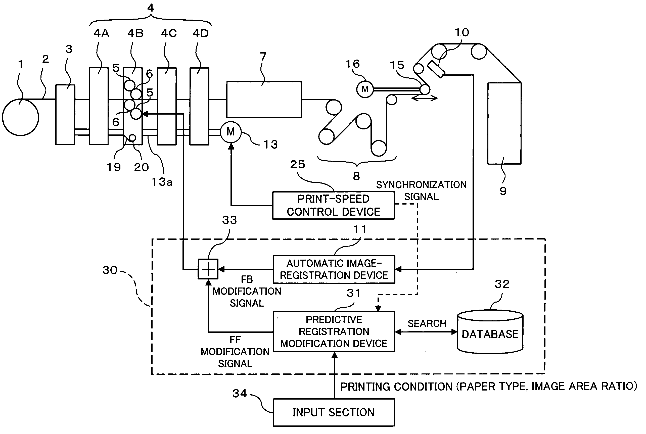
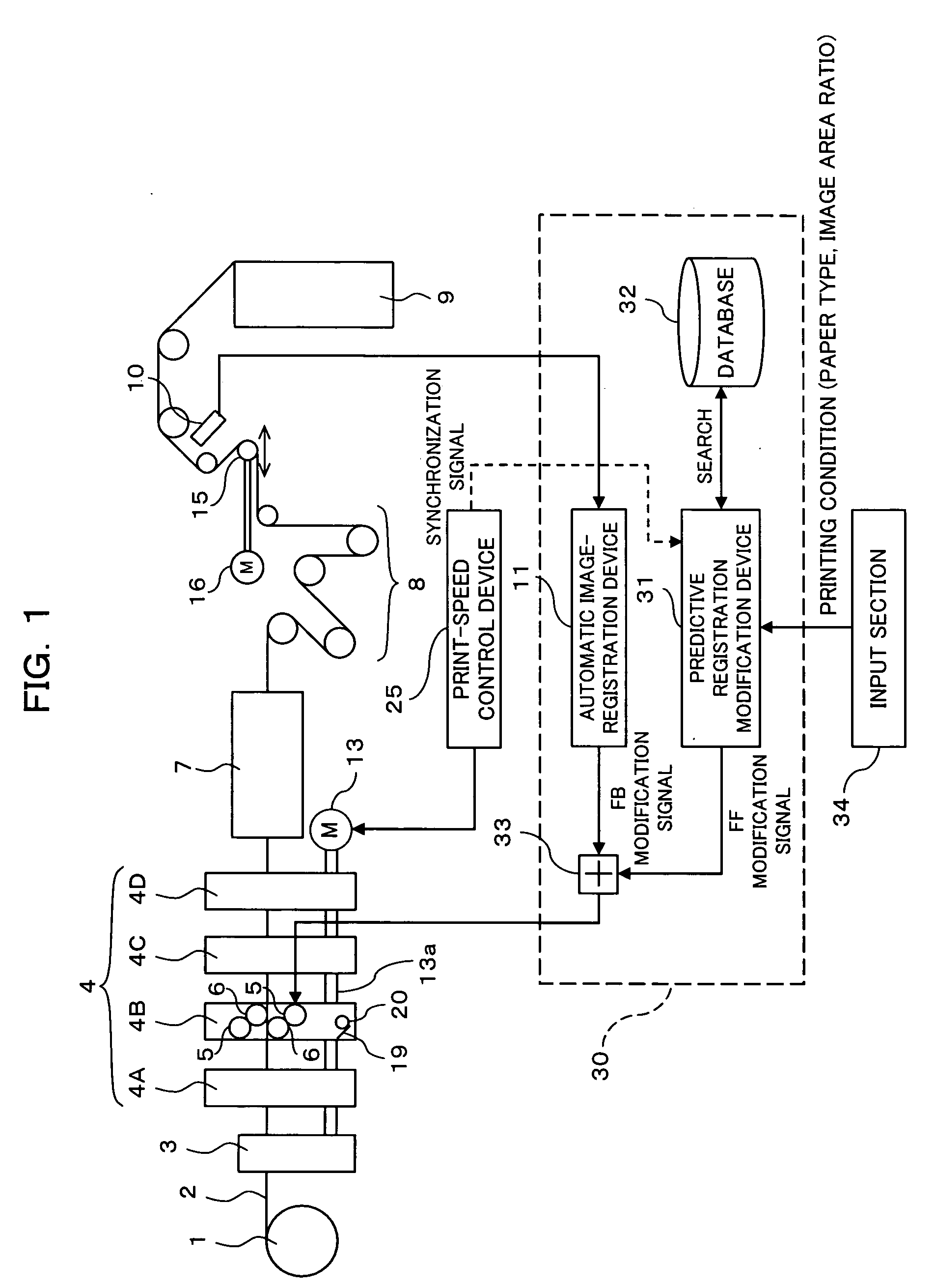
[0086]FIG. 1 is a schematic diagram showing the arrangement of a rotary printing machine according to the first embodiment of the present invention. As shown in FIG. 1, the rotary printing machine according to the present embodiment differs from the conventional rotary printing machine shown in FIG. 16 only in arrangement of the control device, being identical in arrangement of the main body of the printing machine. It is to be noted, however, that FIG. 1 is strictly for the purpose of simplifying the explanation of the nonessential part of the present invention, and does not signify that the registration control method according to the present invention is limitedly applied to the rotary printing machines with such arrangement.

[0087] The rotary printing machine according to the present embodiment has a predictive registration modification device 31 in addition to the conventional automatic image-registration device (automatic registration modification means) 11...

second embodiment

(B) Second Embodiment

[0104]FIG. 6 is a schematic diagram showing the arrangement of a rotary printing machine according to the second embodiment of the present invention. As shown in FIG. 6, the rotary printing machine according to the present embodiment differs from the conventional rotary printing machine shown in FIG. 18 only in arrangement of the control device, being identical in arrangement of the main body of the printing machine. It is to be noted, however, that FIG. 6 is strictly for the purpose of simplifying the explanation of the nonessential part of the present invention, and does not signify that the registration control method according to the present invention is limitedly applied to the rotary printing machines with such arrangement.

[0105] The rotary printing machine according to the present embodiment has a predictive registration modification device (predictive cut-registration modification means) 41 in addition to the conventional automatic cut-registration devi...

third embodiment

(C) Third Embodiment

[0124]FIG. 10 is a schematic diagram showing the arrangement of a rotary printing machine according to the third embodiment of the present invention. As shown in FIG. 10, the rotary printing machine according to the present embodiment differs from the conventional rotary printing machine shown in FIG. 20 only in arrangement of the control device, being identical in arrangement of the main body of the printing machine. It is to be noted, however, that FIG. 10 is strictly for the purpose of simplifying the explanation of the nonessential part of the present invention, and does not signify that the print density control method according to the present invention is limitedly applied to the rotary printing machines with such arrangement. In FIG. 10, like components as in the conventional printing machine are designated by the same reference numerals.

[0125] The ink supply control device 50 of the rotary printing machine according to the present embodiment has a new sp...


PUM


Abstract

A fluctuation characteristic of registration between images printed by individual printing units (4A, 4B, 4C, 4D) while changing print speed is predicted for each of particular printing conditions that affect the registration fluctuation characteristic. Based on the predicted fluctuation characteristic of registration, a control characteristic of the phase between plate cylinders (5, 5, 5, 5) of the individual printing units (4A, 4B, 4C, 4D) is preliminarily set so as to compensate for vertical image misregistration between images printed by the individual printing units (4A, 4B, 4C, 4D), and is stored in a database (32). Then, when the print speed is being changed, from among the plural phase control characteristics thus preliminarily stored in the database (32), a phase control characteristic that corresponds to a printing condition concerning the current printing is selected, and the phase relation between the plate cylinders (5, 5, 5, 5) of the individual printing units (4A, 4B, 4C, 4D) is being modified according to the selected phase control characteristic. Thereby vertical image misregistration can be suppressed and the occurrence of brokes due to the change of print speed can be prevented.

Description

TECHNICAL FIELD [0001] The present invention relates to control techniques concerned with change of print speed in a printing machine, and specifically, relates to a technique of controlling a multi-color rotary printing machine having plural printing units so as to suppress misregistration between images printed by the individual printing units while changing print speed, a technique of controlling a rotary printing machine having a cutting device for cutting a paper web with printed images at regular intervals into individual specified areas at a speed synchronized with print speed so as to suppress cut misregistration of the cutting device while changing print speed, and a technique of controlling a printing machine in which ink is supplied from an ink supply device via plural ink rollers to a plate cylinder so as to suppress fluctuation in print density while changing print speed. BACKGROUND ART [0002]FIG. 16, FIG. 18, and FIG. 20 are schematic block diagrams each illustrating t...

Claims


Application Information

Patent Timeline
Patent Type & Authority Applications(United States)
IPC IPC(8): B41F5/16B41F5/18B41F13/12
CPCB41P2233/10B41F13/12
Inventor NOBUKAWA, SATOSHIMAKINO, SHIGEOSENOO, SHINICHIROHAMAMOTO, YOSHITAKA
Owner MITSUBISHI HEAVY IND LTD
Why Eureka
Try Eureka