Supercharge Your Innovation With Domain-Expert AI Agents!

Roller valve lifter

a roller valve and roller technology, applied in the field of roller valve lifters, can solve the problems of generating substantial heat from friction, flat lifters becoming inadequate, and extremely high wear of cam lobes and lifters, and achieve the effects of reducing friction, simple and economical, and reducing friction

Inactive Publication Date: 2006-01-12
SCHUBECK JOSEPH J
View PDF17 Cites 24 Cited by
  • Summary
  • Abstract
  • Description
  • Claims
  • Application Information

AI Technical Summary

Benefits of technology

"The patent text describes a new valve lifter design for internal combustion engines that reduces friction, avoids excessive wear, and incorporates an improved lubricating system. The valve lifter includes a cylindrical roller and a lifter body with a curved roller socket and tapered end portions. The roller is laterally retained in the roller socket and rolls upon an eccentric cam. The lifter also includes a lubricant passageway for delivering lubricating fluid to the region between the roller surface and the bearing surface. The technical effects of this design include reduced friction, improved fuel efficiency, and reduced wear and tear on the valve lifter."

Problems solved by technology

This construction was simple, but with production of engines designed for higher operating speeds and having higher valve spring biasing forces, flat lifters became inadequate.
In spite of the use of sufficient lubricating oil, flat lifters experienced extremely high wear of the cam lobe and lifter, and generated substantial heat from the friction.
The cam lobe and lifter surface would be quickly worn down, introducing abrasive debris into the engine, and eventually wearing the lifter to the point that the valve action would no longer allow the engine to run properly.
However, even when hardened steel or chrome steel were used, the friction-induced wear on the cam and lifter were found to be excessive.
This condition was exacerbated by the difficulty of providing sufficient lubricating oil to the sliding surface.
Consequently, these attempts were generally unsuccessful, and radius lifters were long ago abandoned in favor of roller valve lifters.
Unfortunately, the needle bearings and axles are frequently unable to withstand the high frequency, high impact load of the rotating cam, and tend to fracture, spreading sharp metal debris throughout the engine.
This is a main cause of frequent failures in roller bearing valve lifters used in high-performance engines.
Additionally, the wheel, axle, and other portions of typical roller valve lifters make them relatively complicated, costly, and heavy.

Method used


Image

  • Roller valve lifter
  • Roller valve lifter
  • Roller valve lifter

Examples


Embodiment Construction

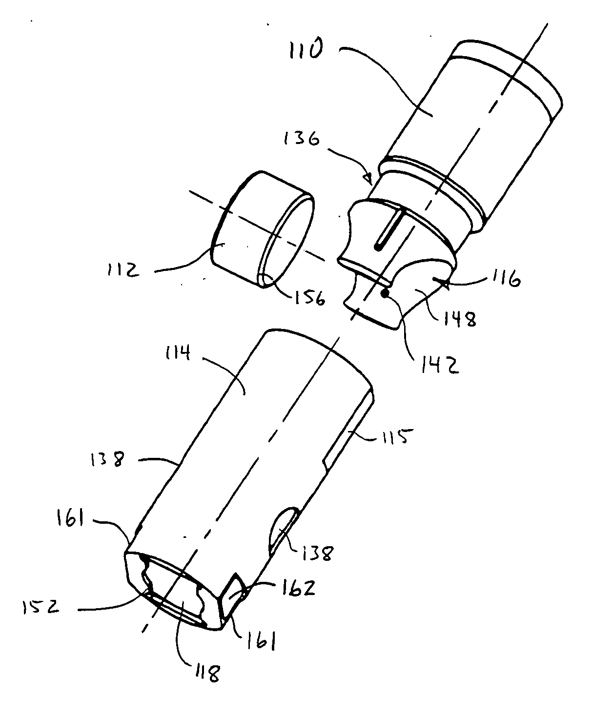
[0027] Reference will now be made to the exemplary embodiments illustrated in the drawings, and specific language will be used herein to describe the same. It will nevertheless be understood that no limitation of the scope of the invention is thereby intended. Alterations and further modifications of the inventive features illustrated herein, and additional applications of the principles of the inventions as illustrated herein, which would occur to one skilled in the relevant art and having possession of this disclosure, are to be considered within the scope of the invention.

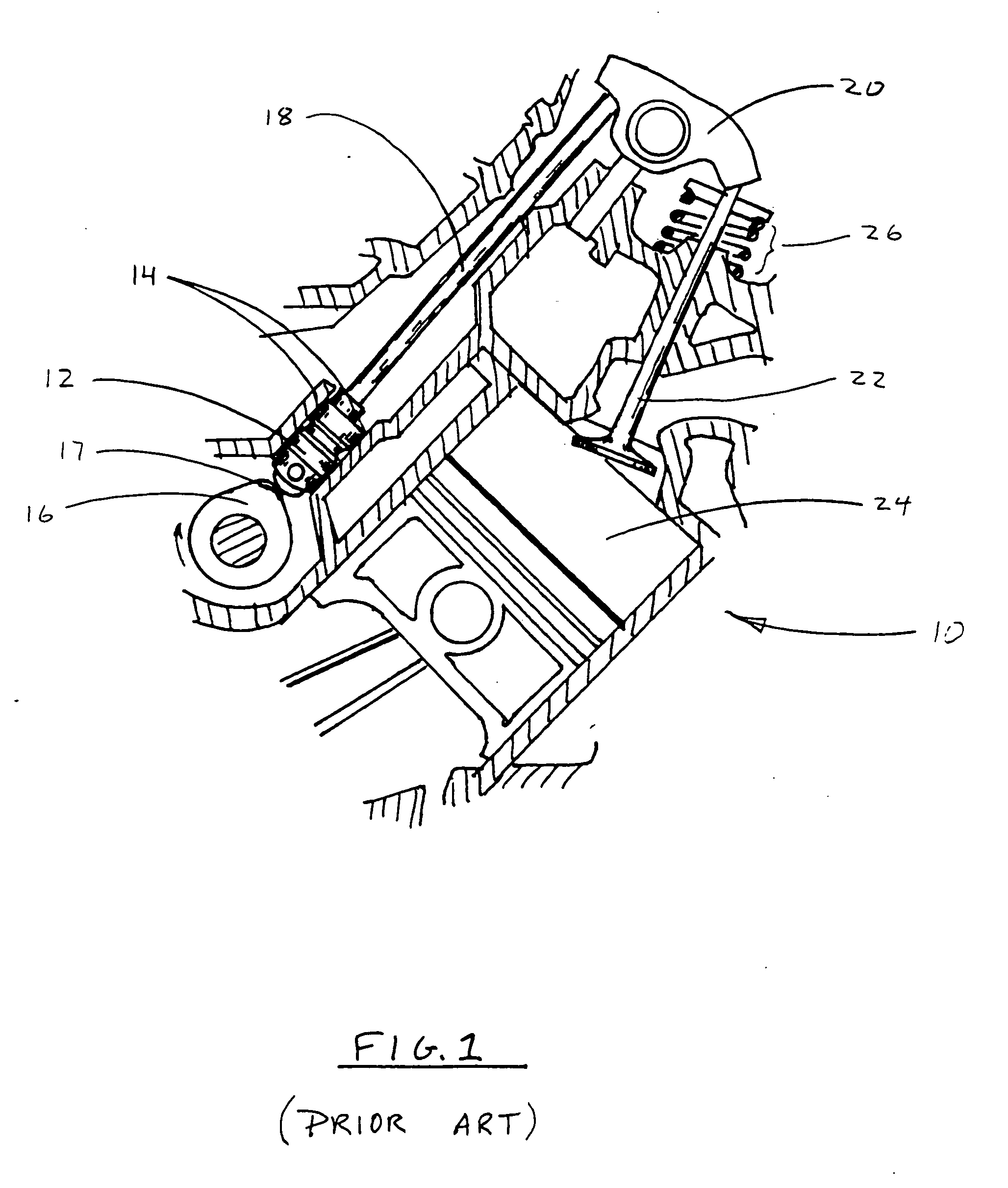
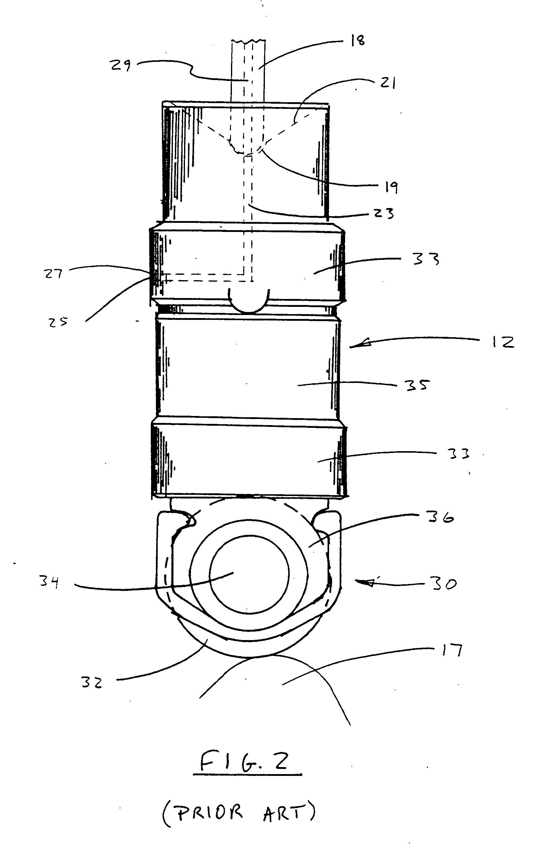
[0028]FIG. 1 is a partial cross-sectional fragmented view of a typical valve lifter shown in operational relationship within the valve assembly of a typical internal combustion engine 10. The valve lifter 12 is disposed within a cylindrical valve lifter bore 14 with its lower end held in contact with a cam 16. The top of the valve lifter is connected to a push rod 18 which is connected to a rocker arm 20 which ...


PUM


Abstract

A roller valve lifter apparatus for following an eccentric cam in an internal combustion engine includes a cylindrical roller, configured to roll upon the eccentric cam, and a lifter body, having a curved roller socket configured to retain the roller and to allow rotation of the roller in the roller socket upon a layer of lubricating fluid trapped between the roller surface and a bearing surface of the roller socket. In one embodiment the roller socket includes tapered end portions defining distal gaps between the roller surface and the bearing surface, for allowing entry of splash oil therebetween.

Description

[0001] The present application claims priority from U.S. Provisional Patent Application Ser. No. 60 / 587,627, filed on Jul. 8, 2004.BACKGROUND OF THE INVENTION [0002] 1. Field of the Invention [0003] This invention relates to valve lifters for actuating push rods in internal combustion engines. More particularly, the present invention relates to an improved roller valve lifter that requires no conventional ball bearing for the roller. [0004] 2. Related Art [0005] Internal combustion engines typically comprise a pair or more of valves associated with each cylinder for intake and exhaust, which open and close to take in fuel and air, and to allow exhaust gasses to escape following combustion. These valves are typically opened and closed by the rotation of a camshaft comprising a plurality of eccentric cams disposed on a shaft which rotates synchronously with the engine. Associated with each valve is a valve lifter, which is in contact with one cam of the camshaft and aligned perpendicu...

Claims


Application Information

Patent Timeline
Patent Type & Authority Applications(United States)
IPC IPC(8): F01L1/14
CPCF01L1/146F01L2101/00F01L2105/02F01L2103/00F01L2101/02F01L2810/02F01L2301/00F01L2301/02F01L2303/00F01L2305/02
Inventor SCHUBECK, JOSEPH J.
Owner SCHUBECK JOSEPH J
Features
  • R&D
  • Intellectual Property
  • Life Sciences
  • Materials
  • Tech Scout
  • Unparalleled Data Quality
  • Higher Quality Content
  • 60% Fewer Hallucinations
Learn More