Forming die for contact lens and contact lens manufacturing method using the forming die

a technology of contact lens and forming die, which is applied in the direction of dough shaping, manufacturing tools, applications, etc., can solve the problems of forming gap between the annular edge portion and the abutting face, difficult to provide stable closure at the peripheral portion of the forming cavity, and risk of burrs or other molding defects occurring at the peripheral edge of the contact lens molding, etc., to achieve effective and stably closure, high accuracy

Inactive Publication Date: 2006-01-12
MENICON CO LTD
View PDF9 Cites 25 Cited by
  • Summary
  • Abstract
  • Description
  • Claims
  • Application Information

AI Technical Summary

Benefits of technology

[0036] As will be apparent from the preceding description, in the contact lens forming die of construction according to the present invention, during mating, the male and female dies are positioned with high accuracy on a center axis by tubular fitter portions, and are stably closed at wide mutual contact areas formed to the outer peripheral side of the forming cavity. Additionally, by putting to good use polymerization shrinkage of the polymerizable monomer exerted on the forming cavity formed on the inner peripheral side of the mutual contact areas and on the auxiliary cavity formed on the outer peripheral side, abutting force of the male and female dies in the mutual contact areas can be effectively and stably achieved. Thus, at the mating faces of the male and female dies, it is possible to form the forming cavity with high accuracy and stability, and thus contact lenses of the desired shape can be molded with high accuracy and stability.

Problems solved by technology

The former forming die provided with the edge portion taught in Patent Citations 3-5 has the drawback that since the peripheral portion of the forming cavity only comes into abutment over a miniscule zone at the distal edge of the edge portion, it is difficult to provide stable closure at the peripheral portion of the forming cavity, and that even slight relative tilting of the male and female dies can result in a gap forming between the annular edge portion and the abutting face.
This results in the risk of burrs or other molding defects occurring at the peripheral edge of the contact lens molding.
In the latter forming die provided with the annular rim projection taught in Patent Citation 6, since it is difficult to form such a thin annular rim projection on the forming die, there is the problem that manufacture of the forming die per se is complicated and expensive.
Additionally, since the annular rim projection is thin and easily deformable, it is difficult for it to assume a consistent shape during abutment, and there is risk that due to slight relative tilting of the male and female dies, the distal edge of the annular rim projection may jut out into the interior of the forming cavity, making it difficult to achieve adequate molding stability.

Method used


Image

  • Forming die for contact lens and contact lens manufacturing method using the forming die
  • Forming die for contact lens and contact lens manufacturing method using the forming die
  • Forming die for contact lens and contact lens manufacturing method using the forming die

Examples


Embodiment Construction

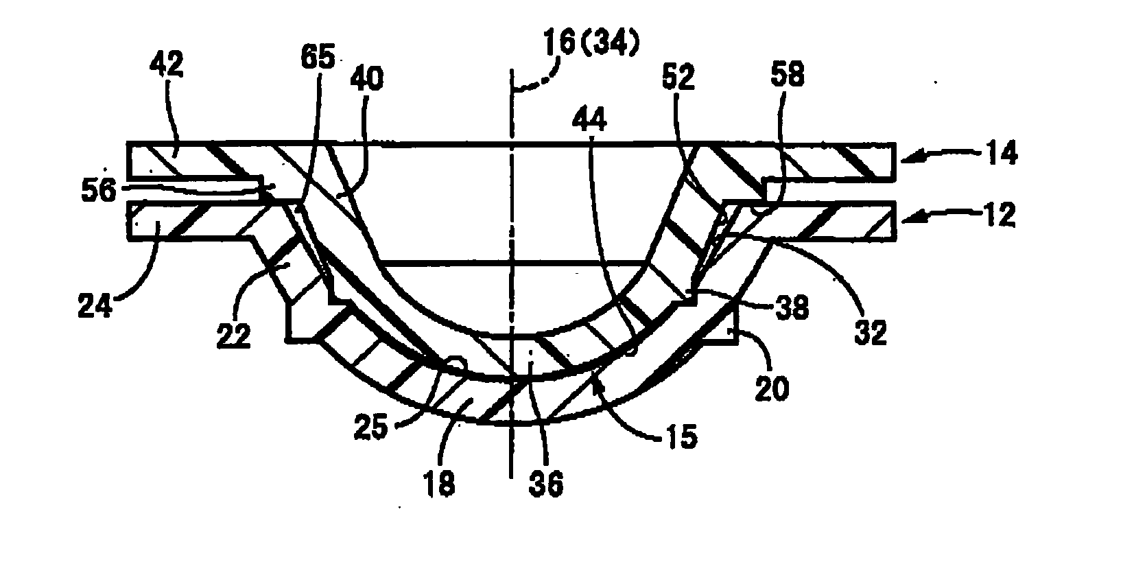
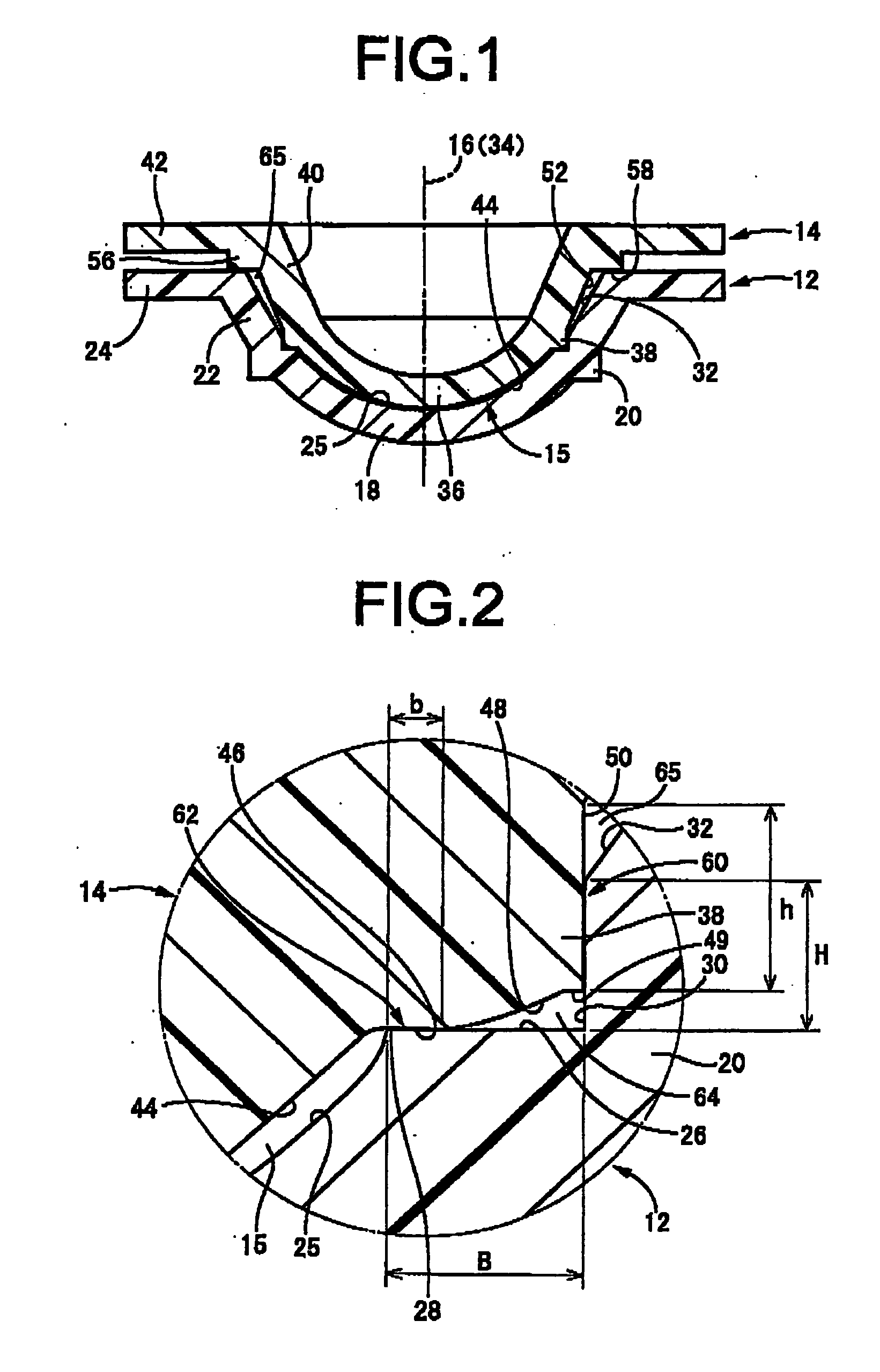
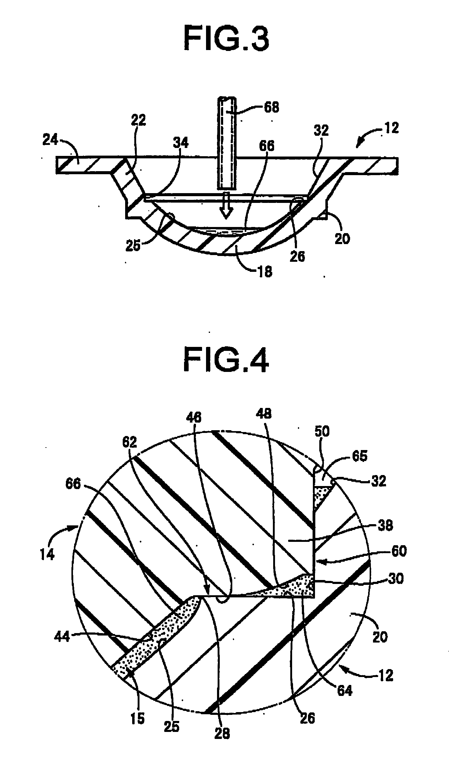
[0019] The invention in a first mode thereof is a contact lens forming die comprising a female die having a concave forming face and a male die having a convex forming face, which are mated with each other to create a forming cavity between the opposed concave forming face and convex forming face, the forming cavity adapted to be filled with polymerizable monomer which is polymerized to form a contact lens, characterized in that by means of mating the female die and the male die with each other, annular flat mutual contact areas extending over a width of 0.01 mm or greater in a direction orthogonal to a die mating direction are formed by abutting the female and male dies at an outer peripheral side of the concave forming face and the convex forming face; and at an outer peripheral side of the mutual contact areas an auxiliary cavity of substantially closed structure to be filled with the polymerizable monomer during molding is formed by the female and male dies positioned spaced apa...


PUM

PropertyMeasurementUnit
widthaaaaaaaaaa
shrinkageaaaaaaaaaa
temperatureaaaaaaaaaa

Abstract

A forming die for a contact lens, wherein flat mutual contact areas (62) allowed to abut on each other on the outer peripheral side of a contact lens forming cavity (15) are formed to have a width of 0.01 mm or wider under the condition that a female die (12) mates a male die (14), a generally closed auxiliary cavity (64) filled with a polymerization monomer (66) is formed on the outer peripheral side of the mutual contact areas (62), and a tubular fitted part (60) allowing both the female and male dies (12) and (14) to be fitted to each other by tubular surfaces (30) and (50) extending in the die mating direction is formed on the outer peripheral side of the auxiliary cavity (64), whereby the forming cavity can be stably formed in the closed state by mating both the male and female dies each other so that the contact lens can be accurately and stably molded while preventing defective molding such as burrs.

Description

TECHNICAL FIELD [0001] The present invention relates to a contact lens forming die for manufacturing contact lenses by a molding process, and to a contact lens manufacturing method employing it. More particularly, the present invention relates to a contact lens forming die, whereby closure can be stably provided to the lens edge portion in the forming cavity, and whereby it possible to consistently obtain mating fixation force of the male and female forming dies, so as to stably carry out molding of the desired contact lens. Also, the present invention relates to a contact lens manufacturing method employing the forming die. BACKGROUND ART [0002] The molding process is one type of manufacturing method that has been used to date for both hard contact lenses and soft contact lenses. The molding process as taught, for example, in Patent Citation 1 or Patent Citation 2, involves mating a female die having a concave forming face with a male die having a convex forming face to produce a c...

Claims


Application Information

Patent Timeline
Patent Type & Authority Applications(United States)
IPC IPC(8): B29D11/00B29C33/00B29C39/02B29C39/28
CPCB29C33/0038B29C33/0055B29C39/02B29L2011/0041B29D11/00125B29K2105/0002B29C39/28B29D11/00038B29D11/0049B29D11/005B29D11/00576
Inventor YAMADA, SEIJI
Owner MENICON CO LTD
Why Eureka
Try Eureka