Device for transferring a pattern to an object

a technology of pattern and transfer device, which is applied in the field of transfer pattern, can solve the problems of product uselessness, device displacement, and inability to use the pattern transferred to the object, and achieve the effect of simple design and high accuracy of the alignment of the stamp

Inactive Publication Date: 2006-01-12
OBDUCAT AB SE
View PDF30 Cites 42 Cited by
  • Summary
  • Abstract
  • Description
  • Claims
  • Application Information

AI Technical Summary

Benefits of technology

[0014] Hereby is obtained a device of a simple design, which has a high accuracy of the alignment of the stamps in relation to the object, thus during operation of the device the displacement, which occurs in the prior art, is limited to an almost imperceptible level inside the limits of accuracy, which is necessary when the pattern is transferred at the same time to both the first surface and the second surface of the object.
[0015] During operation of the device according to the present invention the pressing means is pressing the first stamp into contact with the first surface of the object in a pressing direction. Throughout this movement the alignment means is control

Problems solved by technology

Especially due to the fact that the high requirements in accuracy, when manufacturing micro and nanostructures, in the alignment between the stamp and the object, there is a great need for exact control of the movement of the stamp in the direction perpendicular to the pressing direction, as a small displacement of the stamp can have the severe consequence that the pattern transferred to the object cannot be used.
During this heat transmission an uneve

Method used


Image

  • Device for transferring a pattern to an object
  • Device for transferring a pattern to an object
  • Device for transferring a pattern to an object

Examples


first embodiment

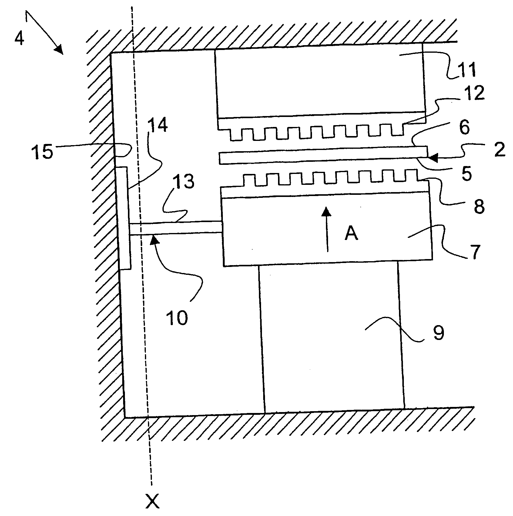
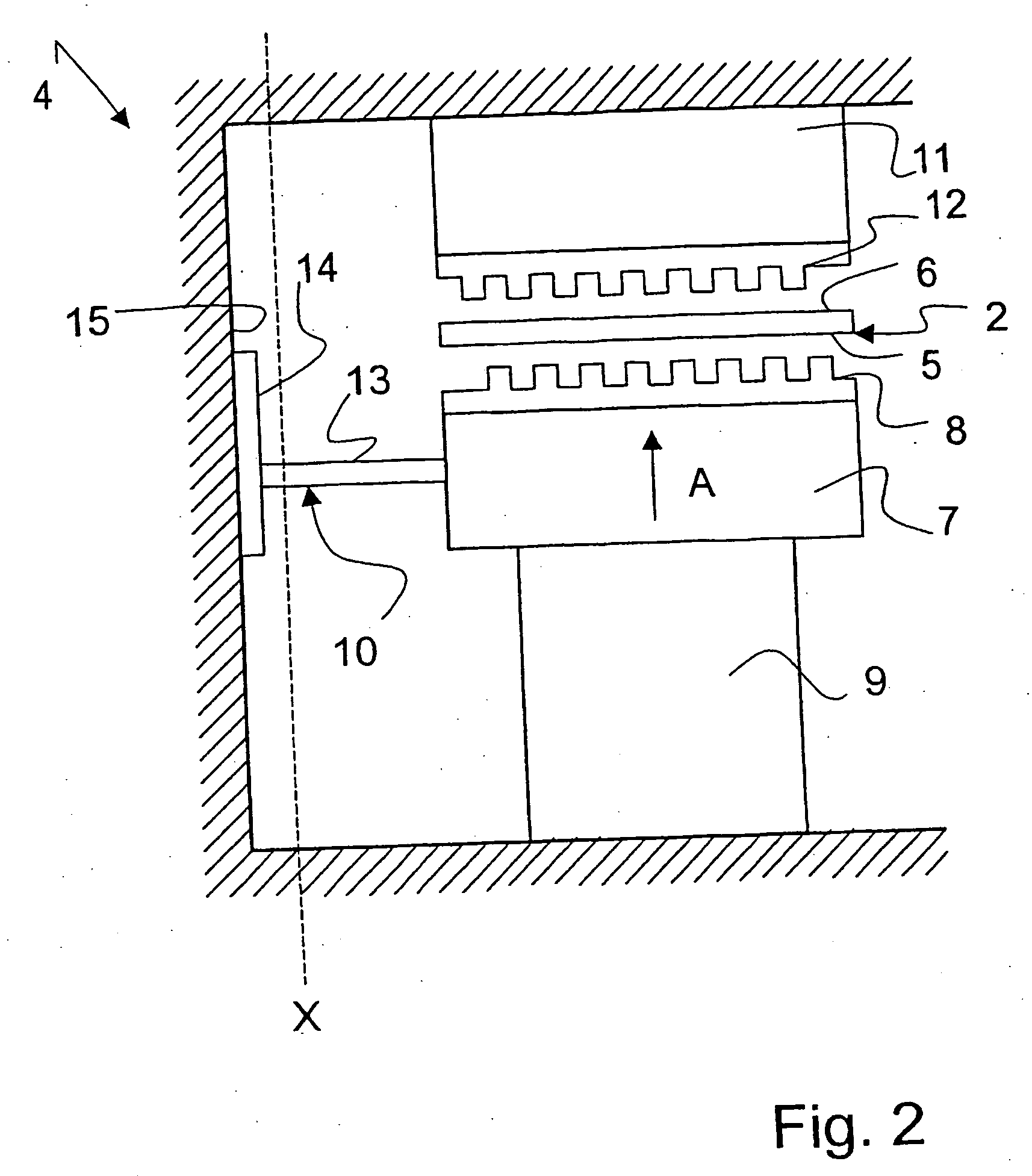
[0033]FIG. 2 is a schematic view of a device according to the invention. The device 4 for transferring a pattern to the object 2, said object 2 having a first surface 5 and a second surface 6, said device 4 comprising a first contacting means 7 having a first stamp 8 adapted to imprint a first pattern in the first surface 5 of the object 2.

[0034] A pressing means 9 is furthermore adapted to press the first stamp 8 into contact with the first surface 5 of the object 2 in a pressing direction, indicated by arrow A. The pressing direction is in this embodiment shown as a vertical movement of the pressing means 9, however, it may also according to the invention be horizontal or inclined movements, which will be appreciated by the skilled person. The pressing means 9 can be of a prior-art type, such as a hydraulically or pneumatic operated press. However, according to the invention the the pressing means may be arranged as mechanically operating means, such as a jack or a screw, whereby ...

second embodiment

[0040]FIG. 3 is a schematic view of a device 4 according to the invention. In this device 4 alignment means 10 is also arranged in connection with the second contacting means 11. In this embodiment the size of the contacting means 7 and 11 is furthermore substantially identical.

[0041] The device may also according to the invention comprise heating means (not shown) arranged for heating the object to a predetermined temperature. The temperature of the object may be heated to 500° C., preferably between 250 and 350° C., most preferably between 280 and 320° C.

[0042] Further a temperature sensor (not shown) may be adapted to monitor the temperature of the object 2 during the pressing.

[0043] Especially with these high temperatures applied to the object 2, it is required to control in an exact manner the heat transfer from the object 2 to the surroundings, i.e. the stamps 8 and 12 as well as the contacting means 7 and 11. If the heat transfer is not controlled this could have severe con...


PUM

PropertyMeasurementUnit
Temperatureaaaaaaaaaa

Abstract

A device (4) for transferring a pattern to an object (2). The invention relates especially to production of micro and nanostructures. The device comprises an alignment means (10) arranged in connection with a first contacting means (7) for controlling the motion of the first stamp (8) in a direction perpendicular to the pressing direction (A), and a second contacting means (11) having a second stamp (12) adapted to imprint a second pattern in the second surface (6) of the object (2), and a pressing means (9) further adapted to press the second stamp (12) into contact with the second surface (6) of the object (2) in the pressing direction (A). Hereby is obtained a device of a simple design, which has a high accuracy of the alignment of the stamps in relation to the object.

Description

FIELD OF THE INVENTION [0001] The present invention relates generally to transferring a pattern from a stamp to an object. The invention relates especially to production of micro- and nanostructures. BACKGROUND ART [0002] A promising technique of producing nanostructures, i.e. structures in the order of 100 nm and smaller, is so-called nanoimprint lithography, however this technique may also be used to microstructures. This technique is described in the document U.S. Pat. No. 5,772,905, which is incorporated herewith by reference. In such lithography, the main steps of which are schematically shown in FIGS. 1a-d, a pattern of nanostructures is transferred from a stamp 1 to an object 2. The object 2 consists of a substrate 2a and, applied thereto, a film 2b of a polymer material (resist). After heating of the film 2b to a suitable temperature, the stamp 1 is pressed into the same (FIG. 1b). The stamp 1 is then released from the object 2 when recesses 3 of a desired depth have been fo...

Claims


Application Information

Patent Timeline
IPC IPC(8): B28B11/08B29C59/00G03F7/00B81C99/00G11B5/855H01L21/027
CPCB29C59/022B29C2059/023B82Y10/00B82Y40/00G11B5/855G03F9/00G03F9/7003G03F9/7042G03F9/7053G03F7/0002
Inventor OLSSON, LENNARTANDERSSON, PETER
Owner OBDUCAT AB SE
Why Eureka
Try Eureka