Linear driving device

a driving device and linear technology, applied in the direction of mechanical energy handling, electrical apparatus, dynamo-electric machines, etc., can solve the problems of difficult use of sine waves as electromotive voltage, affecting the smoothness of the drive, and affecting the precision positioning and smooth feeding of the drive, so as to reduce the cogging force, suppress the pitching, and suppress the cogging force

Inactive Publication Date: 2006-01-12
FANUC LTD
View PDF3 Cites 13 Cited by
  • Summary
  • Abstract
  • Description
  • Claims
  • Application Information

AI Technical Summary

Benefits of technology

[0016] The present invention reduces a cogging force with a simple structure utilizing elements of a driving mechanism of an existing structure. Moreover, the present invention copes with a plurality cogging waveforms having different cycles. Furthermore, the present invention suppresses not only the cogging force but also pitching that is vertical oscillation.
[0017] The present invention reduces a cogging force using slotted coils which are advantageous in that electromotive voltage of sine waves can be adopted, to enable smooth drive, control with quick response because of high rigidity of coil modules, and effective use of the magnets by narrowing gaps so that manufacturing cost is lowered.

Problems solved by technology

The cogging force hampers the precision positioning and the smooth feeding.
In the slotless, coreless motor, however, it is difficult to use sine waves as electromotive voltage.
Accordingly, there is a problem in terms of smoothness of the drive.
Another problem is that low rigidity between the coils and the machine makes it difficult to perform fast response control.
As a result, there is the problem that the cost for improvement is increased.
Besides the problem of a cogging force that acts in a proceeding direction, the linear motor has another problem that there generates minute fluctuation with respect to a direction different from the proceeding direction, that is to say, a direction orthogonal to the proceeding direction (horizontal direction or vertical direction), which is produced in sync with the cogging force.
In a liner drive device, a slide is generally limited in directions other than the proceeding direction.
In the structures described the above documents, the arrangement interval of the armature coils is determined by the pitch of the permanent magnets, which produces the problem that there is no guarantee that a satisfactory suppressing effect is obtained with respect to the cogging force.
Therefore, the method can apply only to cogging waveforms of one kind of cycle, and cannot apply to a plurality of cogging waveforms having different cycles.

Method used


Image

  • Linear driving device
  • Linear driving device
  • Linear driving device

Examples


Embodiment Construction

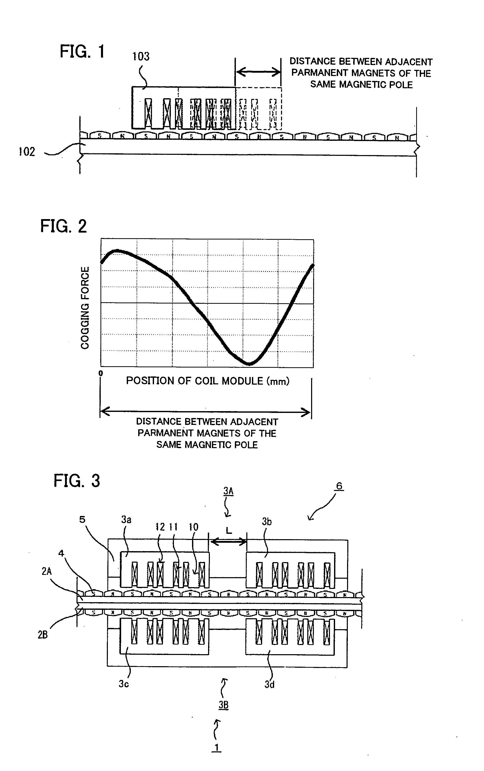
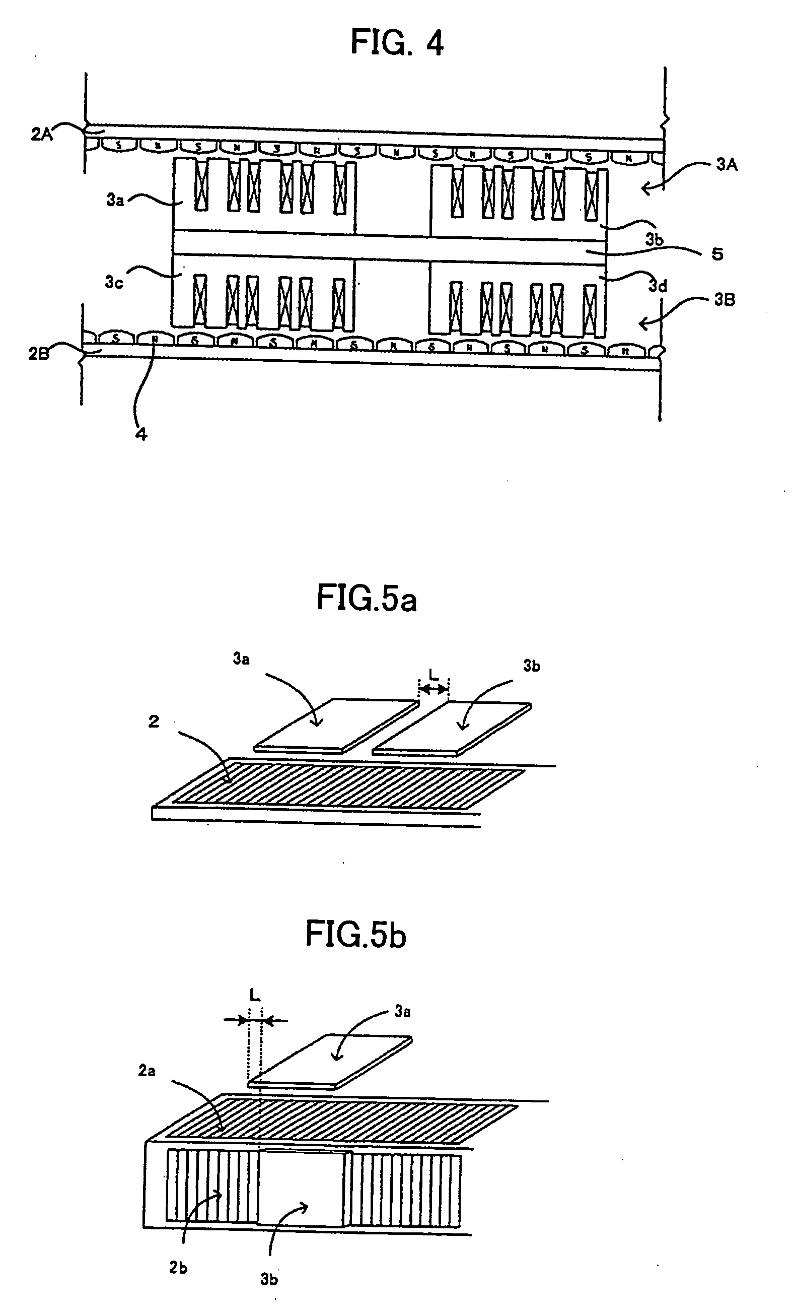
[0041]FIG. 3 is a sectional view for explaining one structure example of a linear driving device according to the present invention. The structure example shown in FIG. 3 is one in which a coil module pair including two coil modules is disposed along each magnet array of a magnet array pair.

[0042] In FIG. 3, a linear driving device 1 is formed of magnet arrays 2A, 2B and coil modules 3a-3d.

[0043] Each of the magnet arrays 2A, 2B are formed by alternately and rectilinearly arranging a plurality of permanent magnets 4 having different polarities. A rectilinear direction in which the permanent magnets 4 are arranged is a displacing direction of a moving body. In the structure example shown in FIG. 3, a first magnet array 2A and a second magnet array 2B are disposed such that magnet poles are located outside.

[0044] An armature block 6 has two coil module pairs 3A and 3B. A coil module pair 3A made up of the first coil module 3a and the second coil module 3b is disposed opposite the f...


PUM


Abstract

A linear driving device that reduces a cogging force with a simple structure as opposed to a drive mechanism having an existing structure, deals with a plurality of cogging waveforms having different periods, and suppresses not only the cogging force but also pitching that is vertical oscillation. The device has a structure provided with a plurality of magnet arrays in which permanent magnets having different polarities are alternately and rectilinearly arranged in the same direction, and a plurality of coil modules having a plurality of teeth and slots fitted with armature coils. The arrangement distance between the coil modules disposed along the displacing direction of each of the magnet arrays equals the sum or remainder of the length corresponding to a half of any one of periods possessed by the cogging force generated when the coil modules move by one magnetic pole and an integer multiple of the length of a magnetic pole pair. The coil modules are connected to each other by a connecting member, and the connecting member makes relative motion along the magnet arrays.

Description

BACKGROUND OF THE INVENTION [0001] 1. Field of the Invention [0002] The present invention relates to a linear driving device, and more specifically to a device that performs linear drive by causing coil modules to make relative motion with respect to permanent magnets of a linear motor or the like. The linear driving device can be used as an actuator for table feeding and the like of a machine tool or as a drive mechanism of a transport device. [0003] 2. Description of Related Art [0004] In some cases, a linear driving device is provided as an actuator for table feeding and the like of a machine tool or as a drive mechanism of a transport device. [0005] Known as such a drive mechanism is a drive mechanism of a linear motor or the like for causing armature blocks to make relative motion with respect to permanent magnets that are rectilinearly disposed. In this linear motor, there generates a cogging force attributable to the surface shapes of the permanent magnets and the shapes of s...

Claims


Application Information

Patent Timeline
Patent Type & Authority Applications(United States)
IPC IPC(8): H02K41/00H02K41/03
CPCH02K29/03H02K41/031H02K2213/03H02K1/278H02K2207/03H02K1/146
Inventor KAWAI, TOMOHIKOEBIHARA, KENZOMINAMI, HIROSHISOGABE, MASATOYOSHIMURA, YOSHIFUMI
Owner FANUC LTD
Why Eureka
Try Eureka