Microplate storage apparatus and method

a micro-plate and storage device technology, applied in the direction of supporting apparatus, chemistry apparatus and processes, domestic applications, etc., can solve the problems of a significant fraction of the total cost of the crystallizer, the manual process of protein crystallization experiments is labor and time-intensive, and the crystallization rate is often very slow

a micro-plate and storage device technology, applied in the direction of supporting apparatus, chemistry apparatus and processes, domestic applications, etc., can solve the problems of a significant fraction of the total cost of the crystallizer, the manual process of protein crystallization experiments is labor and time-intensive, and the crystallization rate is often very slow

US20060006774A1Inactive Publication Date: 2006-01-12KENDRO LAB PRODS

Image

  • Microplate storage apparatus and method
  • Microplate storage apparatus and method
  • Microplate storage apparatus and method

Examples


Embodiment Construction

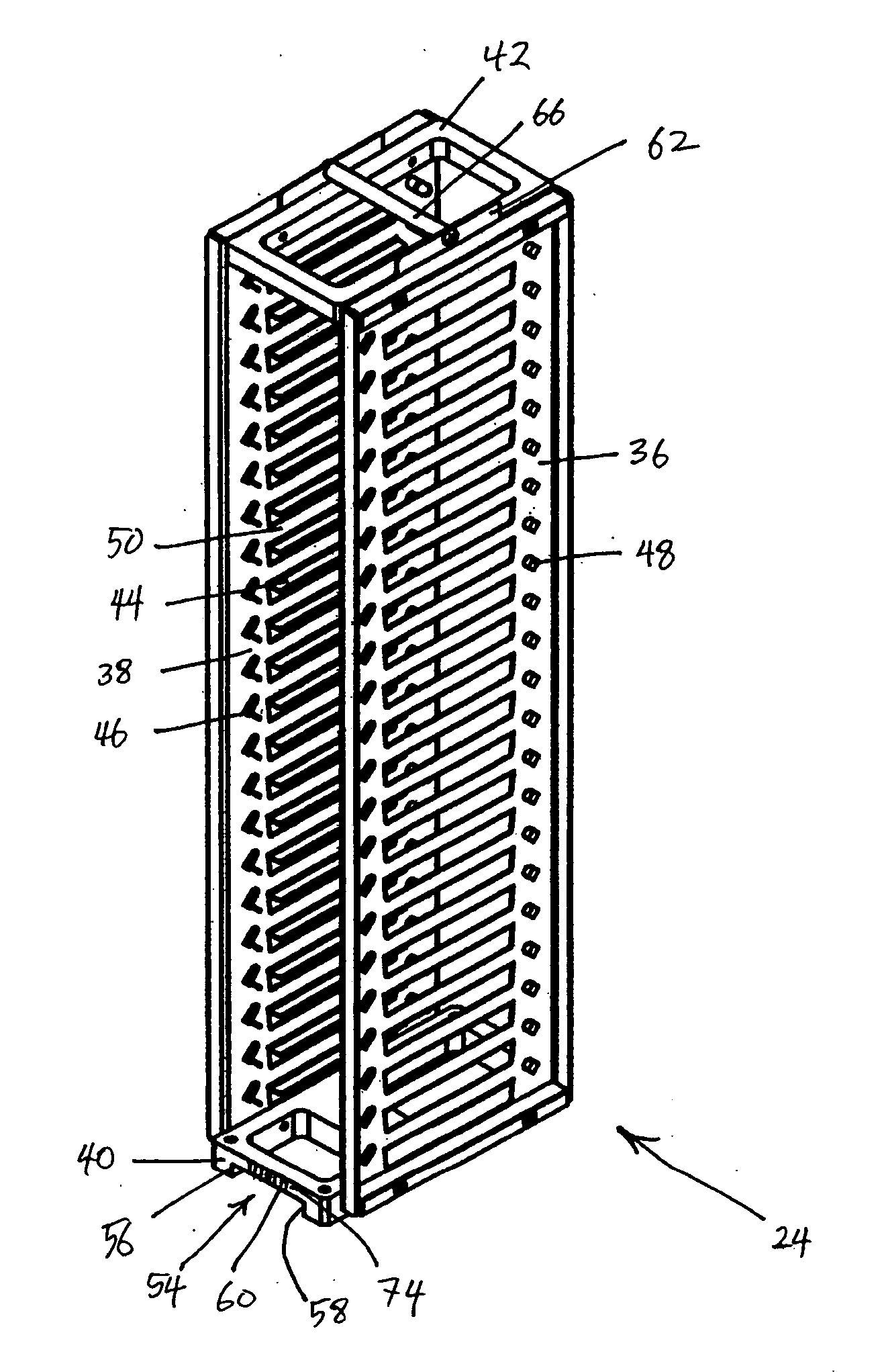
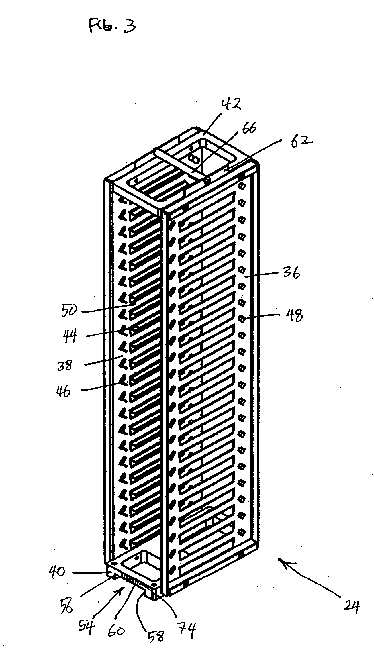
[0025] The invention will now be described with reference to the drawing figures, in which like reference numerals refer to like parts throughout. An embodiment in accordance with the present invention provides a way to store microplates in a high density and cost effective manner in a complex instrument. Furthermore, some embodiments also provide a way to determine the position, alignment and registration of a microplate storage hotel relative to other hotels and to the instrument's frame.

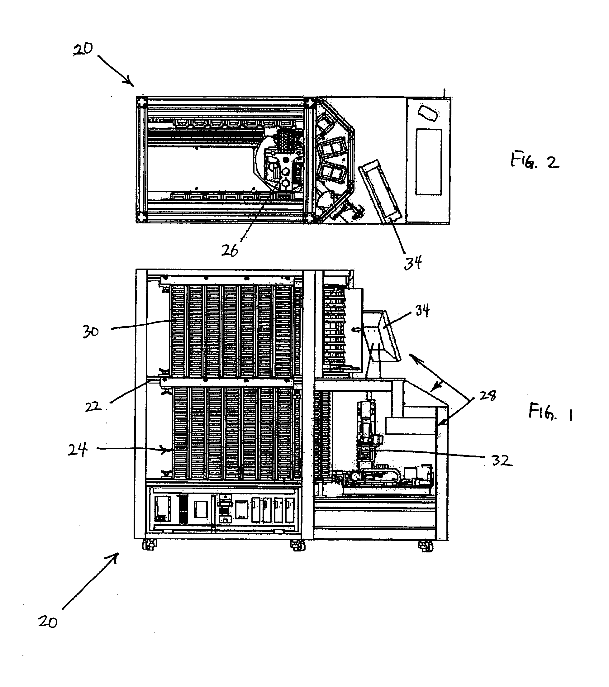
[0026]FIG. 1 shows a side view of an automated plate storage and imaging apparatus 20 for protein crystallization. The apparatus 20 has a system frame 22 that supports the housing of multiple microplate storage hotels 24. A robotic microplate handler 26 shown in FIG. 2, controlled by a computer system 28, is used to transfer a microplate 30 to the imager 32. The computer system 28 has a monitor 34 and is used to analyze the data collected by the imager 32. The imager 32 can take images under brig...


PUM


Abstract

An embodiment of the invention has a side panel with integrated shelving members and integrated locating members, both folded from the side panel. One method of fabricating the shelving members involves cutting a template of the shelving members and locating members onto the side panel and then folding the cut portions of the side panel to form shelving members and locating members.

Description

FIELD OF THE INVENTION [0001] The present invention relates generally to storage devices. More particularly, the present invention relates to microplate storage devices. BACKGROUND OF THE INVENTION [0002] Determining and achieving the proper conditions that allow a protein to crystallize from solution often requires many attempts before the proper concentrations of protein and reagents is determined and achieved. Furthermore, even when the conditions permit crystallization, the rate of crystallization is often very slow, at times on the order of weeks or even months. As a result, manually performing protein crystallization experiments is a very labor and time intensive process. One method of increasing the chances of obtaining protein crystals in the first experiment, thus saving a significant amount of time, is to try as many different protein and reagent concentrations as possible in the initial experiment. [0003] Because protein crystallization experiments have traditionally been...

Claims


Application Information

Patent Timeline
12 Jan 2006
Publication
US20060006774A1
IPC
A47B97/00; B01L99/00
CPC
B01L3/06; B01L2300/0829; B01L2300/021; B01L9/523; B01L2200/025
Inventors
JACKSON, JON; GREENWAY, R. BRYAN JR.