Circuit arrangement having a full bridge with switching load relief for operating lamps

a technology of operating lamp and switch, which is applied in the direction of light sources, lighting apparatus, instruments, etc., can solve the problem that switching load relief is only rarely possible in the case, and achieve the effect of low circuit complexity

Inactive Publication Date: 2006-01-12
PATENT TREUHAND GESELLSCHAFT FUR ELECTRIC GLUEHLAMPEN MBH
View PDF10 Cites 6 Cited by
  • Summary
  • Abstract
  • Description
  • Claims
  • Application Information

AI Technical Summary

Benefits of technology

[0008] The invention therefore makes possible a single-stage circuit arrangement for operating a lamp having low circuit complexity, in the case of which the lamp current can be set via the above-described phase shift, and the energy balance in the charge pump can be set via the operating frequency, all of the switches provided being relieved of load.

Problems solved by technology

Since lamps often need to be operated in a frequency range which is prescribed by the lamp technology, and, in addition, the inductive component of the load resistance is prescribed by inductors for current limitation purposes, switching load relief is only rarely possible in the case of full bridges from the prior art during lamp operation.

Method used


Image

  • Circuit arrangement having a full bridge with switching load relief for operating lamps
  • Circuit arrangement having a full bridge with switching load relief for operating lamps
  • Circuit arrangement having a full bridge with switching load relief for operating lamps

Examples


Embodiment Construction

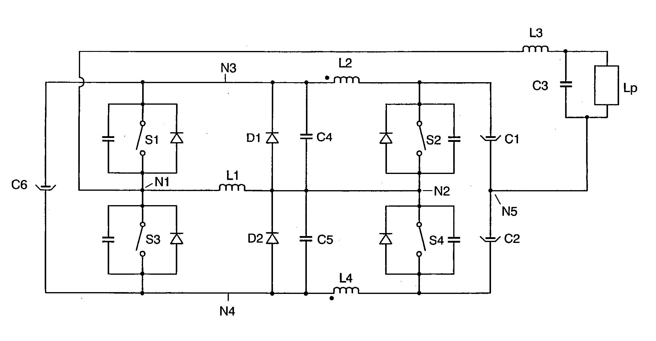
[0016]FIG. 1 shows a circuit arrangement according to the invention. In the text which follows, the topology of this circuit arrangement is described.

[0017] A first full-bridge branch comprises the series circuit comprising a first and a third electronic switch S1, S3 which are connected at a first center point N1. A second full-bridge branch comprises the series circuit comprising a second and a fourth electronic switch S2, S4 which are connected at a second center point N2.

[0018] The first and the second full-bridge branch are each connected with one connection to a positive node N3 and with the other connection to a negative node N4. An energy source which feeds in a DC voltage between the positive node N3 and the negative node N4 is not illustrated. A storage capacitor C6 is connected between the positive node N3 and the negative node N4.

[0019] The first and the second center points N1, N2 are connected via a first inductor L1. According to the invention, at least one second ...


PUM


Abstract

The invention relates to a circuit arrangement for operating lamps. The circuit arrangement essentially comprises a full bridge. According to the invention, at least one inductor is connected in series with a full-bridge branch for switching load relief purposes. The circuit arrangement is preferably suitable for operation using a charge pump. PFC is thus achieved in a single-stage arrangement.

Description

FIELD OF THE INVENTION [0001] The invention relates to circuit arrangements for operating lamps. In the present patent application, the term lamp encompasses apparatuses which are suitable for producing electromagnetic radiation having a wavelength of between 50 nanometers and 50 000 nanometers from electrical energy. Examples of such lamps are incandescent lamps, gas discharge lamps or light-emitting diodes. [0002] The circuit arrangement is, in particular, a full bridge, whose switches are relieved of load. Furthermore, the circuit arrangement is also suitable for keeping line current harmonics low. BACKGROUND OF THE INVENTION [0003] Specification U.S. Pat. No. 4,864,479 (Steigerwald) discloses a DC-to-DC converter which is in the form of a full bridge. Parasitic capacitances and diodes of the switches in the full bridge provide load relief for the switches. The switches only switch on when the voltage which is applied to the switches is zero. This is referred to in the literature...

Claims


Application Information

Patent Timeline
Patent Type & Authority Applications(United States)
IPC IPC(8): G05F1/00
CPCH05B41/2856
Inventor FRANCK, FELIXSOWA, WOLFRAM
Owner PATENT TREUHAND GESELLSCHAFT FUR ELECTRIC GLUEHLAMPEN MBH
Why Eureka
Try Eureka