Circuit arrangement for supplying a control electronics system in electric machines

Inactive Publication Date: 2005-12-01
ROBERT BOSCH GMBH
View PDF14 Cites 6 Cited by
  • Summary
  • Abstract
  • Description
  • Claims
  • Application Information

AI Technical Summary

Benefits of technology

[0008] The circuit configuration of the present invention for supplying the control electronics of electrical machines, particularly in starter-generators, having the features of claim 1 has the advantage that the voltage supply for the control electronics is ensured also in operation without battery an

Problems solved by technology

In the case of sufficiently high rotational speeds of the synchronous machines this can lead to an exceeding of the permitted voltage and there is the danger of destroying the electronics of the starter-generator as well as the electrical system electronics.
Since it is possible that the vehicle battery is destroyed during the operation of the vehicle or that the battery is largely drained due to unfavorable circumstances, there is the danger that in

Method used


Image

  • Circuit arrangement for supplying a control electronics system in electric machines
  • Circuit arrangement for supplying a control electronics system in electric machines

Examples


Example

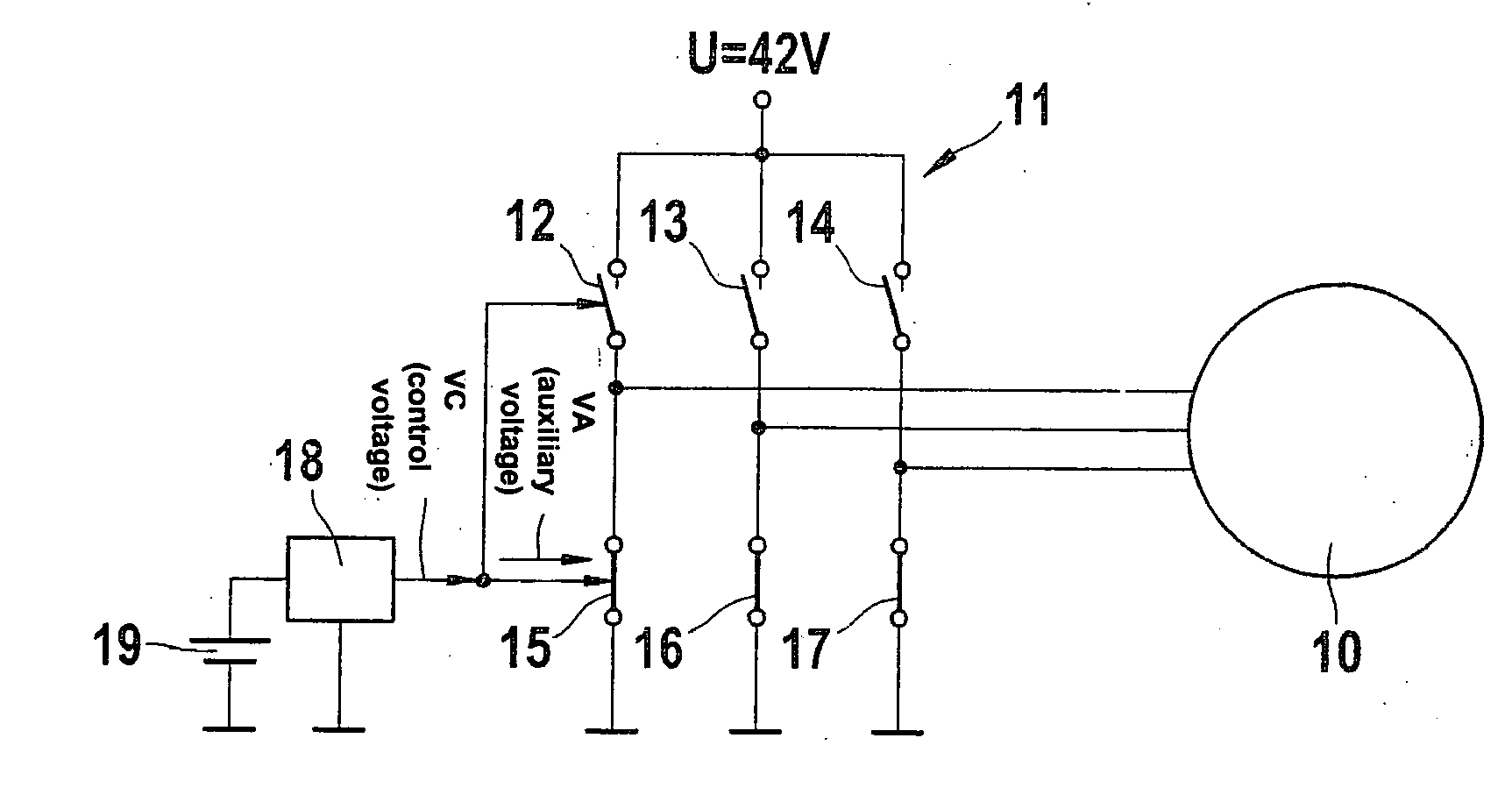
[0014]FIG. 1 shows a rough schematic representation of a voltage supply circuit for an electric machine 10, in which d.c. voltage is supplied to electrical machine 10 via a switchable bridge 11. The switchable bridge here includes three high-side switch elements 12, 13, 14 and three low-side switch elements 15, 16, 17, for example field-effect transistors (MOSFETs) or appropriate pulse-controlled inverter elements etc. and carries on the side opposite to ground a voltage U of 42 volts for example. The electrical machine 10 is connected in the usual manner to the controlled rectifier bridge. The windings of the electrical machine 10 are not represented in FIG. 1.

[0015] The switch elements of the rectifier bridge are suitably controlled by a control electronics 18. The voltage for control electronics 18 is supplied in normal operation from battery 19, via suitable voltage converters if necessary. In the short-circuit case represented in FIG. 1, low-side switch elements 15, 16, 17 are...


PUM


Abstract

A circuit configuration for supplying the control electronics in an electrical machine 10 is specified, which includes a passive transformer circuit 20, which is powered by a phase current IP of the electrical machine 10 and which generates an auxiliary voltage VA that is used for supplying the output stage of the electrical machine if no battery is present or if the battery is defective or discharged.

Description

FIELD OF THE INVENTION [0001] The present invention is based on a circuit configuration for supplying the control electronics of electrical machines and relates in particular to supply circuits for starter-generators in motor vehicles which can also be operated without battery. BACKGROUND INFORMATION [0002] Usually, two electrical machines are used in motor vehicles, a generator, which is driven by the engine of the motor vehicle and which generates electrical energy for supplying the electrical-system consumers and for charging the battery, and a starter, which works as a battery-powered electrical motor and which, in the event of a starting operation, brings the engine of the motor vehicle up to a required minimum rotational speed. Also known, however, are systems featuring a single electrical machine, which takes the form of a starter-generator and which accomplishes both the starting of the engine as well as the generation of the electrical energy. [0003] Such starter-generators...

Claims


Application Information

Patent Timeline
IPC IPC(8): H02P9/00H02P9/04H02P9/30
CPCH02P9/30H02P9/006
Inventor BEULICH, KLAUSPESCH, MICHAEL
Owner ROBERT BOSCH GMBH
Why Eureka
Try Eureka