Cantilever probe with dual plane fixture and probe apparatus therewith

a cantilever probe and fixture technology, applied in the field of cantilever probes, can solve the problems of limited average positioning accuracy of all cantilever probes, impose new challenges, and consume large real estate, and achieve the effects of low real estate consumption, low cost of mass fabrication, and high precision

Inactive Publication Date: 2006-01-12
MICRO PROBE
View PDF8 Cites 9 Cited by
  • Summary
  • Abstract
  • Description
  • Claims
  • Application Information

AI Technical Summary

Benefits of technology

[0006] A cantilever probe has an elbow for bonding to a dual plane fixture plate having two substantially non parallel fixture surfaces in an angle corresponding to the elbow. The dual plane angled fixture between elbow and fixture plate provides for a highly stiff and precise hold of the bonded cantilever probe with minimal real estate consumption. The cantilever probe may feature at least two positioning pins one of which may be placed at the contacting tip and the other one may extend from at least one of two contacting faces of the elbow. The elbow positioning pin may fit into a corresponding elbow pin hole on one of the fixture surfaces. The tip positioning pin may fit into a corresponding tip pin hole of a sacrificial assembly plate temporarily combined with the fixture plate for a precise positioning of the cantilever probes during curing, setting or hardening of a bonding agent between the fixture plate an the elbow. After assembly of a number of cantilever probes, the sacrificial plate may be removed and the tip pins eventually sanded to a common plane.
[0007] Separate fan-out beams may be aligned with beam positioning pins on and attached to the fixture plate. The fan-out beams are aligned and conductively connected with their probe connect ends to respective probe elbows once the cantilever probes are fixed. The fan-out beams in turn may be conductively connected with their respective peripheral connect ends to well known large pitch apparatus terminals of a circuit board. Cantilever probes and fan-out beams may have geometries suitable for inexpensive mass fabrication by well known masked electro deposition fabrication techniques. A probe apparatus may be easily customized by providing varying drill patterns of the positioning holes for fan-out beams and cantilever probes to match pitch requirements of the tested circuit chips.

Problems solved by technology

Continuing miniaturization of cantilever probes imposes new challenges for their positioning and fixing within a probe apparatus.
To provide sufficient positioning accuracy, the fixture portion of the cantilever probe is commonly extensively dimensioned, which in turn consumes extensive real estate forcing multilayer cantilever probe assemblies with varying cantilever geometries.
Such varying cantilever geometries result in different deflection behavior and limited average positioning accuracy of all cantilever probes of a probe apparatus.
In addition, cantilever probes of the prior art are commonly fixed in a surrounding fashion along a linear fixture element, which requires additional surrounding referencing and / or positioning structures, which in turn consume additional space between the cantilever probes.
Peripheral fan-out structures may be a multitude of the cantilever portion, which reduces the positioning accuracy of the ever decreasing cantilevers and contacting tips.

Method used


Image

  • Cantilever probe with dual plane fixture and probe apparatus therewith
  • Cantilever probe with dual plane fixture and probe apparatus therewith
  • Cantilever probe with dual plane fixture and probe apparatus therewith

Examples


Embodiment Construction

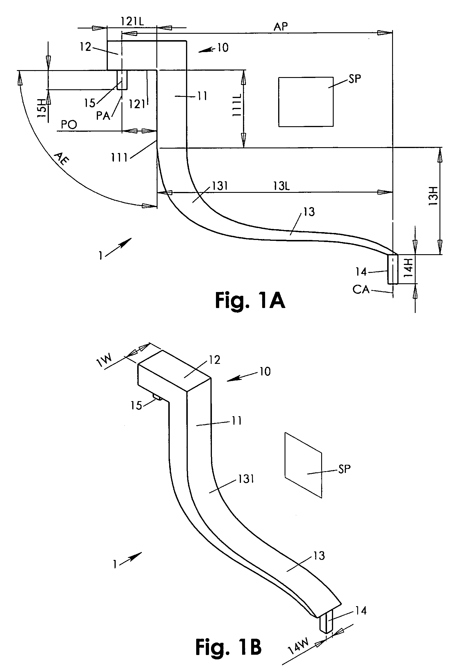
[0017] Referring to FIGS. 1A, 1B, a cantilever probe 1 for test contacting a well known test contact of a tested electronic circuitry along a contacting axis CA may have a tip positioning pin 14 configured for the test contacting. The tip positioning pin 14 may also be configured for an aligning insertion in a respective one of tip pin holes 43A-43N (see FIG. 3) also along the contacting axis CA. The cantilever probe 1 may further feature a cantilever 13 for resiliently holding the tip positioning pin 14 with respect to the contacting axis CA with a predetermined deflection behavior including a well known scrub motion along the symmetry plane SP.

[0018] A base arm 11 may rigidly extend from said cantilever probe 13 such that operational deflection of the cantilever 13 leaves a base arm assembly face 111 substantially free of deformation. An offset arm 12 extends substantially rigid from the base arm 11 in a substantially non parallel elbow angle AE defining together with the base ar...


PUM


Abstract

A cantilever probe has an elbow for bonding to a dual plane fixture plate for a highly stiff and precise angled fixture of the bonded cantilever probe with minimal real estate consumption. The cantilever probe may feature a tip positioning pin and an elbow positioning pin fitting into corresponding holes of the fixture plate and a sacrificial assembly plate. Separate fan-out beams may be attached to the fixture plate and conductively connected to respective elbows once the cantilever probes are fixed. The fan-out beams in turn may be conductively connected with their respective peripheral ends to large pitch apparatus terminals of a circuit board. A probe apparatus may be easily customized by providing varying drill patterns of the positioning holes for fan-out beams and cantilever probes to match pitch requirements of the tested circuit chips.

Description

CROSS REFERENCE [0001] The present invention cross references the U.S. Patent Application of the same inventor January Kister, titled “Freely Deflecting Knee Probe With Controlled Scrub Motion” filed May 21, 2004, application Ser. No. 10 / 850,921, which is hereby incorporated by reference.FIELD OF INVENTION [0002] The present invention relates to cantilever probes. In particular, the present invention relates to a cantilever probe with angle fixture and a probe apparatus therewith. BACKGROUND OF INVENTION [0003] Continuing miniaturization of cantilever probes imposes new challenges for their positioning and fixing within a probe apparatus. Cantilever probes are commonly fixed with their peripheral ends having their cantilever portion with the contacting tip free suspended to provide the required flexibility. To provide sufficient positioning accuracy, the fixture portion of the cantilever probe is commonly extensively dimensioned, which in turn consumes extensive real estate forcing ...

Claims


Application Information

Patent Timeline
Patent Type & Authority Applications(United States)
IPC IPC(8): G01R31/02
CPCG01R1/06733G01R1/06727G01R1/07357G01R1/07342
Inventor KISTER, JANUARY
Owner MICRO PROBE
Why Eureka
Try Eureka