
Dual phase flush urinal

a flushing urinal and dual-phase technology, applied in the field of sanitaryware, can solve the problems of affecting the quantity and affecting the quality of suitable water, and affecting the quality of suitable water, and achieve the effects of overcoming the deficiencies of waterless urinals, sufficient sanitary conditions, and simple installation and maintenan

Inactive Publication Date: 2005-03-08
AS IP HOLDCO LLC
View PDF10 Cites 34 Cited by
  • Summary
  • Abstract
  • Description
  • Claims
  • Application Information

AI Technical Summary

Benefits of technology

The dual-phase flush urinal significantly reduces water consumption by 40% to 80% compared to conventional designs, ensuring cleanliness and odor-free operation with reduced maintenance needs, while maintaining code compliance and aesthetic compatibility with existing fixtures.

Problems solved by technology

The excessive consumption of potable water remains a dilemma for water agencies, commercial building owners, homeowners, residents and sanitaryware manufacturers.
An increasing global population has negatively affected the amount and quality of suitable water.
Effluents in water supplies and increasing air pollutants have drastically altered fresh water supplies.
Many such designs still use an inordinate amount of water to complete a flush cycle, especially in consideration of contemporary water conservation efforts.
Conventional waterless designs, however, do not scour a back wall surface and do not provide a water trap seal as required by plumbing codes in the United States and other jurisdictions.
In addition, omission of the water trap seal in waterless fixtures necessarily omits replenishment of the trap seal after each use, thereby requiring frequent maintenance of the fixtures to maintain satisfactory cleanliness (such as the addition of a liquid medium to provide a seal between the liquid waste and the room, and periodic cartridge replacement).

Method used


Image

  • Dual phase flush urinal
  • Dual phase flush urinal
  • Dual phase flush urinal

Examples


Embodiment Construction

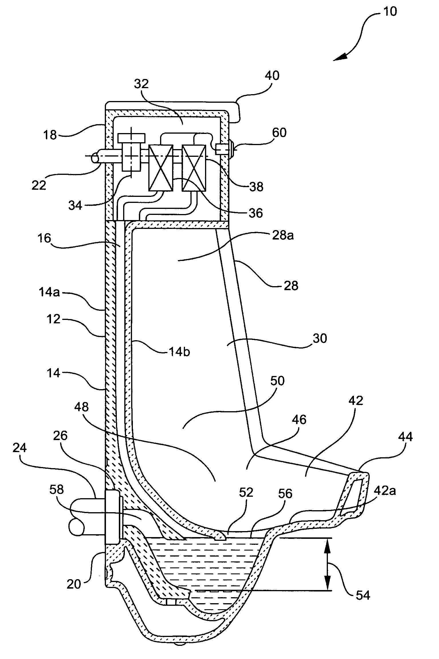
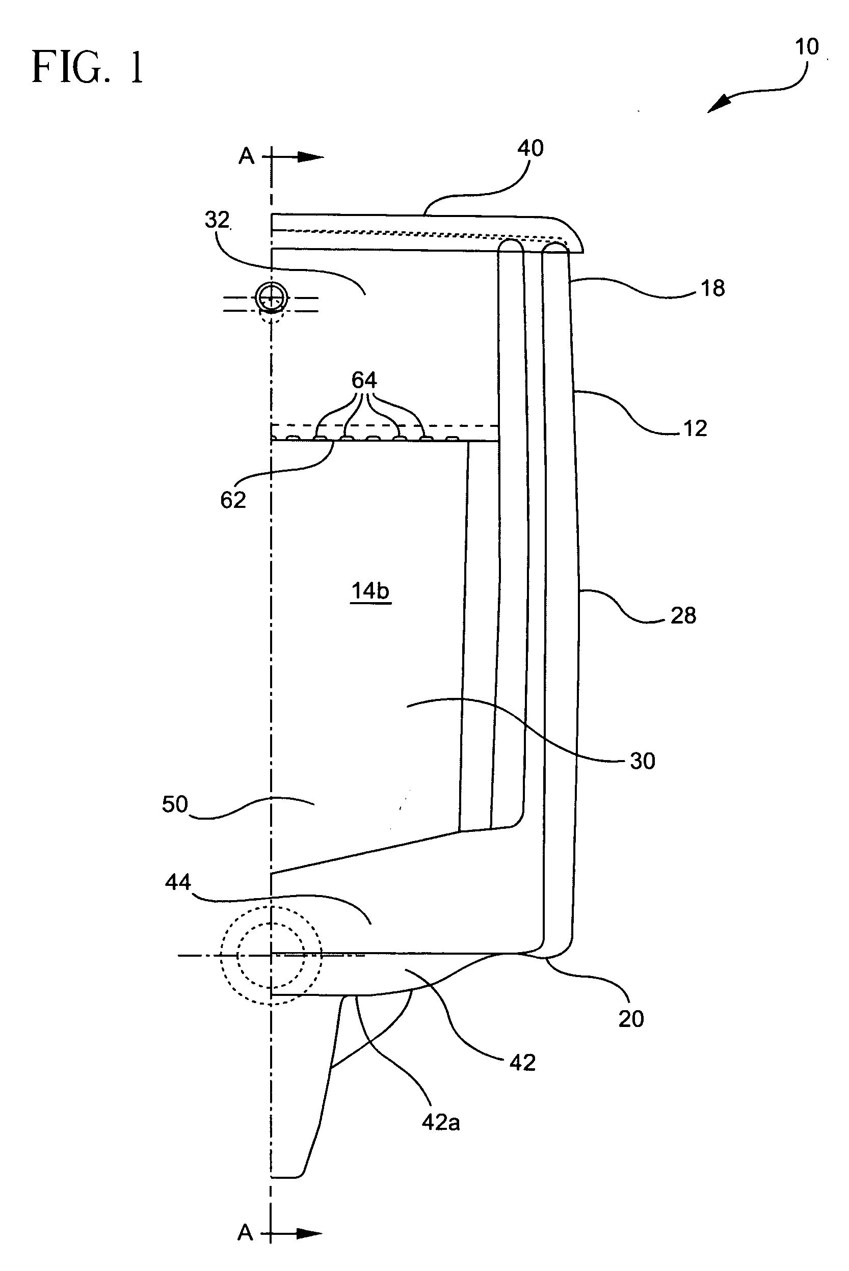
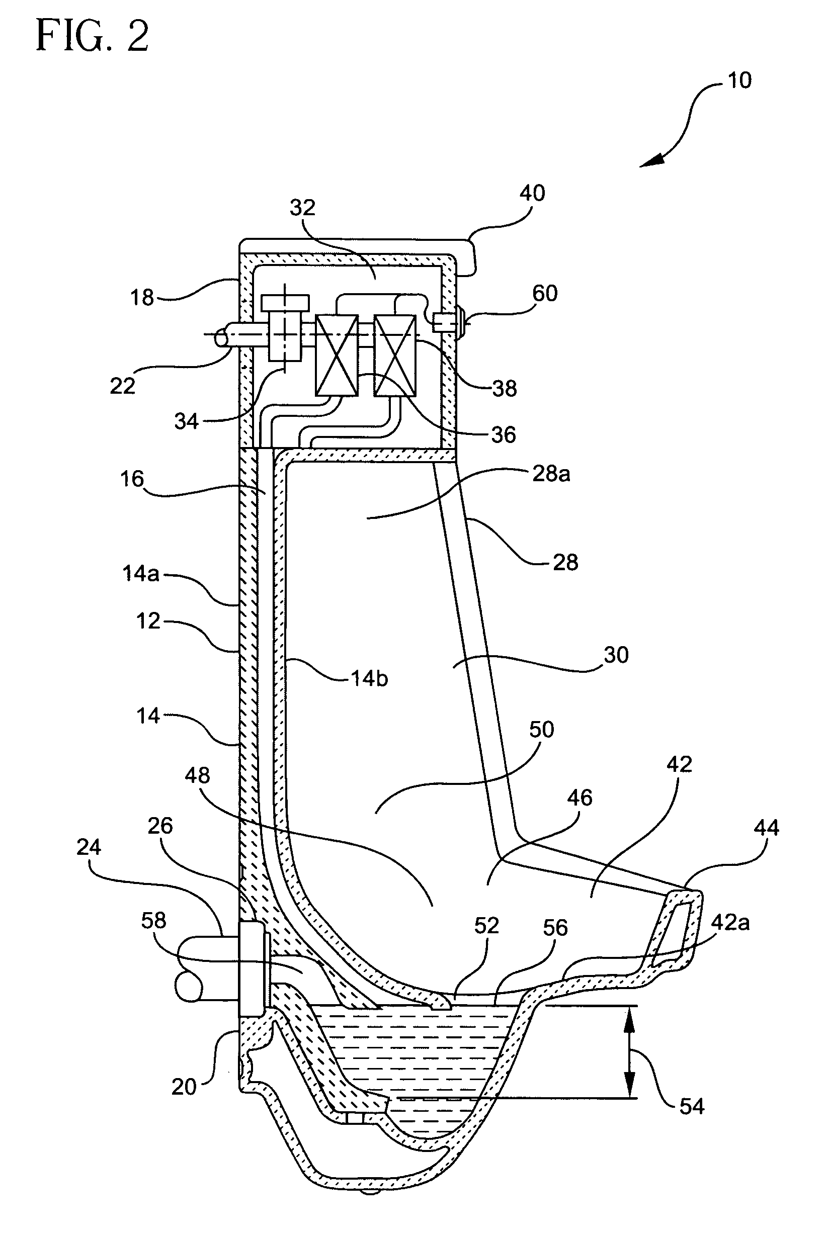
Now referring to the figures and particularly referring to FIG. 1, a urinal 10 of the present invention desirably comprises an integral chinaware fixture 12. Fixture 12 may also be fabricated from plastic, stainless steel or any other material that is amenable to practice of the present invention. Fixture 12 may have one or more treatments applied thereon to enhance the urinal's performance. Such treatments may include coatings or glazes having one or more of hydrophobic, hydrophilic, anti-microbial, antibacterial, biocidal, odor suppressing, anti-viral and algicidal properties. Such coatings are well known within the industry to promote the cleanliness of plumbing fixtures and deter the transmission of undesirable contagions thereby.

Fixture 12 includes a rear wall 14 (shown in FIG. 2) having a mounting surface 14a for mounting of the urinal to a support structure such as a wall and a urinal surface 14b facing the user that serves as a splash surface for the urinal. Intermediate mo...


PUM


Abstract

A dual-phase flush urinal that maintains itself in a sufficiently sanitary condition with minimal water consumption. The urinal includes a piece of chinaware having a rear wall with a pair of sidewalls depending normally outward therefrom. A bottom extent of the sidewalls terminates in a curved bowl portion having a fluid well and a water drain therewithin. The sidewalls and rear wall together define a containment area in which an atmospheric vacuum breaker and valve means are disposed. The valve means is in electrical communication with a sensor that detects the presence of a user and has a first fluid discharge port in fluid communication with the bowl portion and a second fluid discharge port. Upon detection of the user, the sensor transmits a first signal to the valve means to initiate a first water exchange phase of the flush cycle. The first fluid discharge port provides water along an elongate channel to remove waste from the bowl portion. After a preprogrammed delay, the sensor transmits a second signal to the valve means to initiate a subsequent, time-delayed wall-scouring phase of the flush cycle. The second fluid discharge port provides water through a urinal spreader to ensure rinsing of the back surface subsequent to actuation of the jet. The valve means operates according to a desired preprogrammed schedule to ensure delivery of adequate water to the urinal jet and expulsion of waste from the urinal to an exterior sewage system.

Description

FIELD OF THE INVENTION The present invention is directed to sanitaryware that consumes less water than conventional devices yet sustains sufficient hygiene standards. More particularly, the present invention is directed to a urinal that implements valve means having a pair of fluid discharge ports to substantially reduce the amount of water necessary to maintain the urinal in a clean and sanitary condition. In this configuration, the present invention urinal desirably effects water exchange and wall scouring functions on a time delay basis, thereby substantially reducing the amount of water consumed without sacrificing cleanliness. BACKGROUND OF THE INVENTION The excessive consumption of potable water remains a dilemma for water agencies, commercial building owners, homeowners, residents and sanitaryware manufacturers. An increasing global population has negatively affected the amount and quality of suitable water. Effluents in water supplies and increasing air pollutants have drast...

Claims


Application Information

Patent Timeline
Patent Type & Authority Patents(United States)
IPC IPC(8): E03D13/00
CPCE03D13/00
Inventor DEMARCO, PETER V.
Owner AS IP HOLDCO LLC
Learn More