RF filter and method for fabricating the same

a technology of rf filter and rf filter, which is applied in the direction of impedence networks, electrical devices, etc., can solve the problems of difficult to form a thin film having a thickness precisely as designed and the adjustment process is very complicated

Inactive Publication Date: 2006-01-12
PANASONIC CORP
View PDF13 Cites 23 Cited by
  • Summary
  • Abstract
  • Description
  • Claims
  • Application Information

AI Technical Summary

Benefits of technology

[0012] It is therefore an object of the present invention to provide an RF filter in which piezoelectric resonators formed on a substrate are adjusted to have different resonance frequencies without a complicated process and which has a constant frequency characteristic.

Problems solved by technology

However, it is generally difficult to form a thin film having a thickness precisely as designed.
However, adjustment of the resonance frequency of a piezoelectric resonator for obtaining a desired frequency characteristic of an RF filter by the conventional methods has the following problem.
However, the conventional methods only enable all the piezoelectric resonators formed on a substrate to have the same resonance frequency.
Accordingly, adjustment of the piezoelectric resonators by the conventional methods has a problem in which the adjustment process is very complicated.

Method used


Image

  • RF filter and method for fabricating the same
  • RF filter and method for fabricating the same
  • RF filter and method for fabricating the same

Examples


embodiment 1

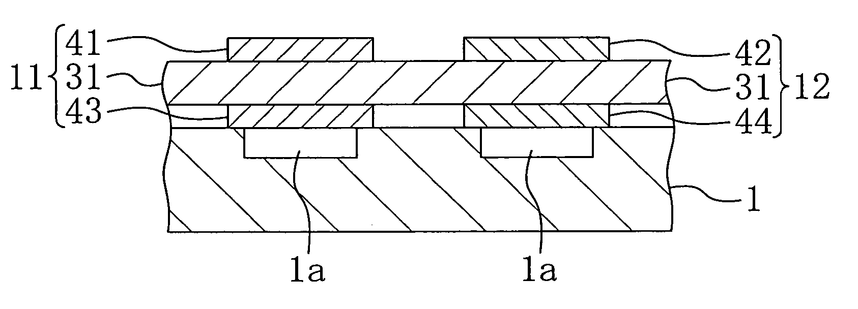
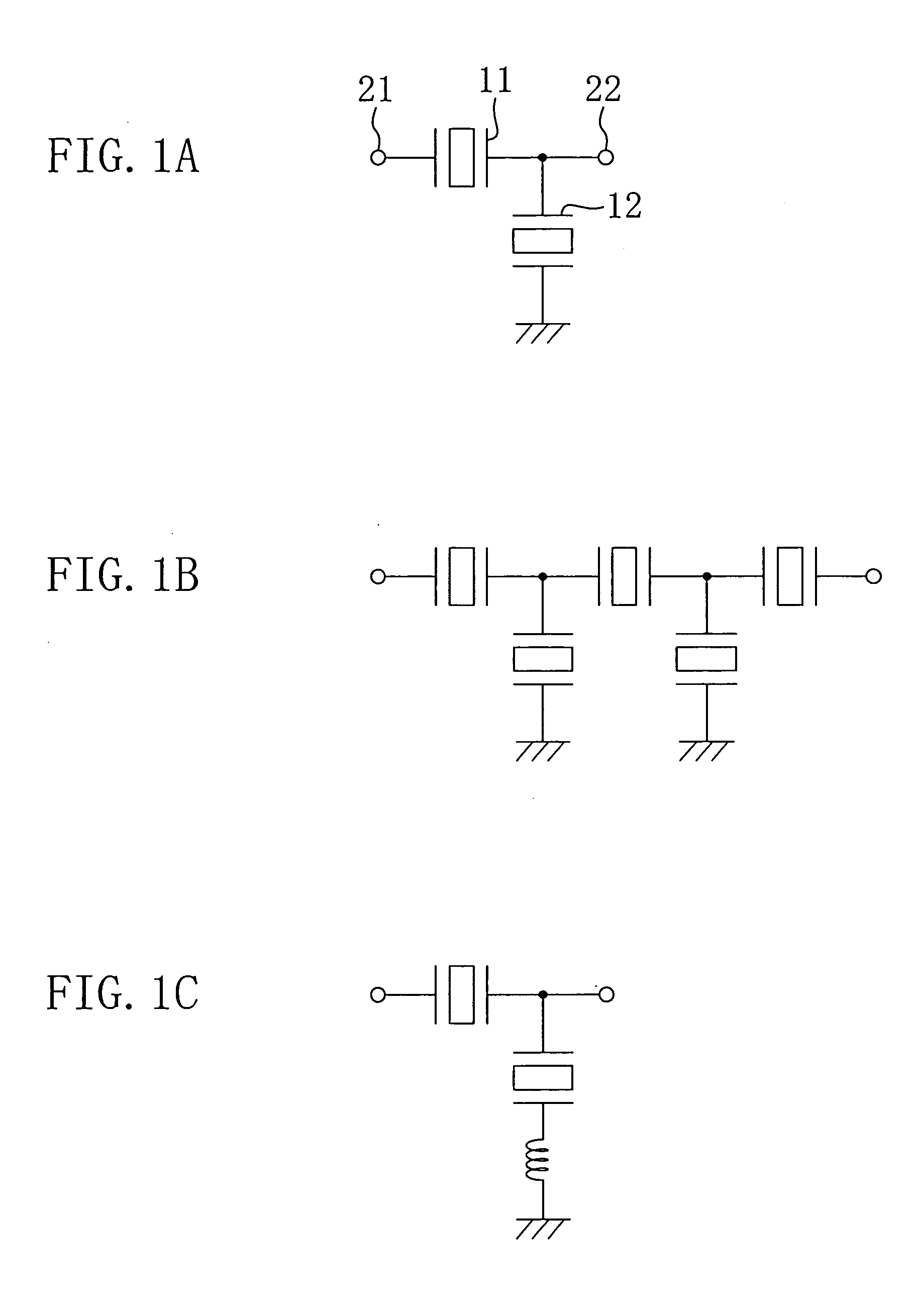
[0046] An RF filter and a method for fabricating the RF filter according to a first embodiment of the present invention will be described with reference to the drawings. FIG. 1A illustrates a basic circuit configuration of the RF filter of this embodiment. As shown in FIG. 1A, a ladder filter is constituted by a first piezoelectric resonator 11 that is a serial element connected between an input / output terminal 21 and an input / output terminal 22 and a second piezoelectric resonator 12 that is a parallel element connected between an output terminal 22 and ground.

[0047] The resonance frequency of the first piezoelectric resonator 11 as a serial element needs to be adjusted to the maximum frequency in a pass band of the RF filter. The resonance frequency of the second piezoelectric resonator 12 as a parallel element needs to be adjusted to the minimum frequency in the pass band of the RF filter. FIG. 1A illustrates a basic unit of the RF filter in which one first piezoelectric resonat...

embodiment 2

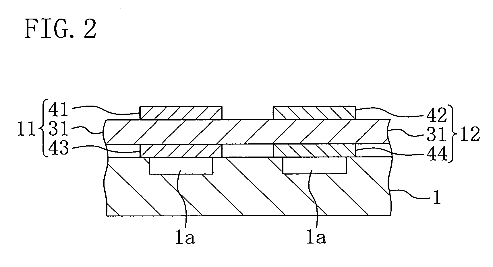
[0076] Hereinafter, an RF filter and a method for fabricating the RF filter according to a second embodiment of the present invention will be described with reference to the drawings. FIG. 8 illustrates cross-sectional structures of piezoelectric resonators for use in the RF filter of the second embodiment. In FIG. 8, components also shown in FIG. 2 are denoted by the same reference numerals, and the description thereof will be omitted.

[0077] The RF filter of the second embodiment is a ladder filter similar to that of the first embodiment and has the same circuit configuration as that shown in FIG. 1A.

[0078] As shown in FIG. 8, in this embodiment, each of a first upper electrode 41, a first lower electrode 43, a second upper electrode 42 and a second lower electrode 44 has a thickness of 400 nm and made of molybdenum (Mo). A first additional film 71 made of a first material is formed on the first upper electrode 41. A second additional film 72 made of a second material is formed o...


PUM


Abstract

An RF filter includes: one or more first piezoelectric resonators each of which is held on a principal surface of a substrate and is constituted by a first piezoelectric film and opposed first upper and lower electrodes provided on the upper and lower faces of the first piezoelectric film, respectively; and one or more second piezoelectric resonators each of which is held on the principal surface of the substrate, is constituted by a second piezoelectric film and opposed second upper and lower electrodes provided on the upper and lower faces of the second piezoelectric film, respectively, and has a resonance frequency different from that of each of the first piezoelectric resonators. At least one of the first upper and lower electrodes is made of a first electrode material and at least one of the second upper and lower electrodes is made of a second electrode material.

Description

CROSS-REFERENCE TO RELATED APPLICATION [0001] This application claims priority under 35 U.S.C. §119 on Patent Application No. 2004-199166 filed in Japan on Jul. 6, 2004, the entire contents of which are hereby incorporated by reference. The entire contents of Patent Application No. 2005-193621 filed in Japan on Jul. 1, 2005 are also incorporated by reference. BACKGROUND OF THE INVENTION [0002] The present invention relates to RF filters using piezoelectric resonators and methods for fabricating the RF filters. [0003] With recent global proliferation of cellular phones, the number of cellular phones in use has been increasing in an accelerated pace. The cellular phones need to process RF signals with different frequencies, and it is generally necessary to remove RF signals with frequencies other than a desired frequency. In a terminal, for example, it is always necessary to remove RF signals other than signals with a target frequency for a circuit called a front end that receives sig...

Claims


Application Information

Patent Timeline
Patent Type & Authority Applications(United States)
IPC IPC(8): H03H9/58H03H9/56
CPCH03H3/04H03H2003/0471H03H2003/0428H03H9/564
Inventor ISHII, MOTONORI
Owner PANASONIC CORP
Why Eureka
Try Eureka