
Radar device

a radar device and a technology of a radar device, applied in the direction of measurement devices, multi-channel direction-finding systems using radio waves, instruments, etc., can solve the problems of insufficient processing speed of the radar device, insufficient amount of data collection, inaccurate estimation, etc., and achieve accurate estimation of the number of incoming waves

Active Publication Date: 2006-01-12
DENSO CORP
View PDF14 Cites 43 Cited by
  • Summary
  • Abstract
  • Description
  • Claims
  • Application Information

AI Technical Summary

Benefits of technology

The present invention provides a method for accurately estimating the number of incoming waves in a radar device using a combination of the MUSIC method and the ESPRIT method. The method includes generating a beat signal, calculating the self-correlation matrix, calculating the eigenvalue, setting a threshold, and estimating the number of incoming waves based on the threshold. The method can also include excluding false estimations and predicting the position of the target object based on the history of detection data. The technical effect of the invention is to improve the accuracy of estimating the number of incoming waves in a radar device.

Problems solved by technology

In other words, the estimation is not accurate when the amount of data is not sufficient.
However, sufficient amount of data can not be collected when an object of detection and the radar device are moving relatively fast toward each other, or processing speed of the radar device is not sufficient.
Further, the SN ratio of the signal in the radar device suffers an influence of a multi-path signal problem when the automobile having the radar device is surrounded by a plurality of radar wave reflecting objects.
In this kind of situation, the radar device in the automobile using the MUSIC method or the ESPRIT method cannot avoid a false detection of the object or an erroneous operation because the estimation of the incoming wave number is not accurate.

Method used


Image

  • Radar device
  • Radar device
  • Radar device

Examples


first embodiment

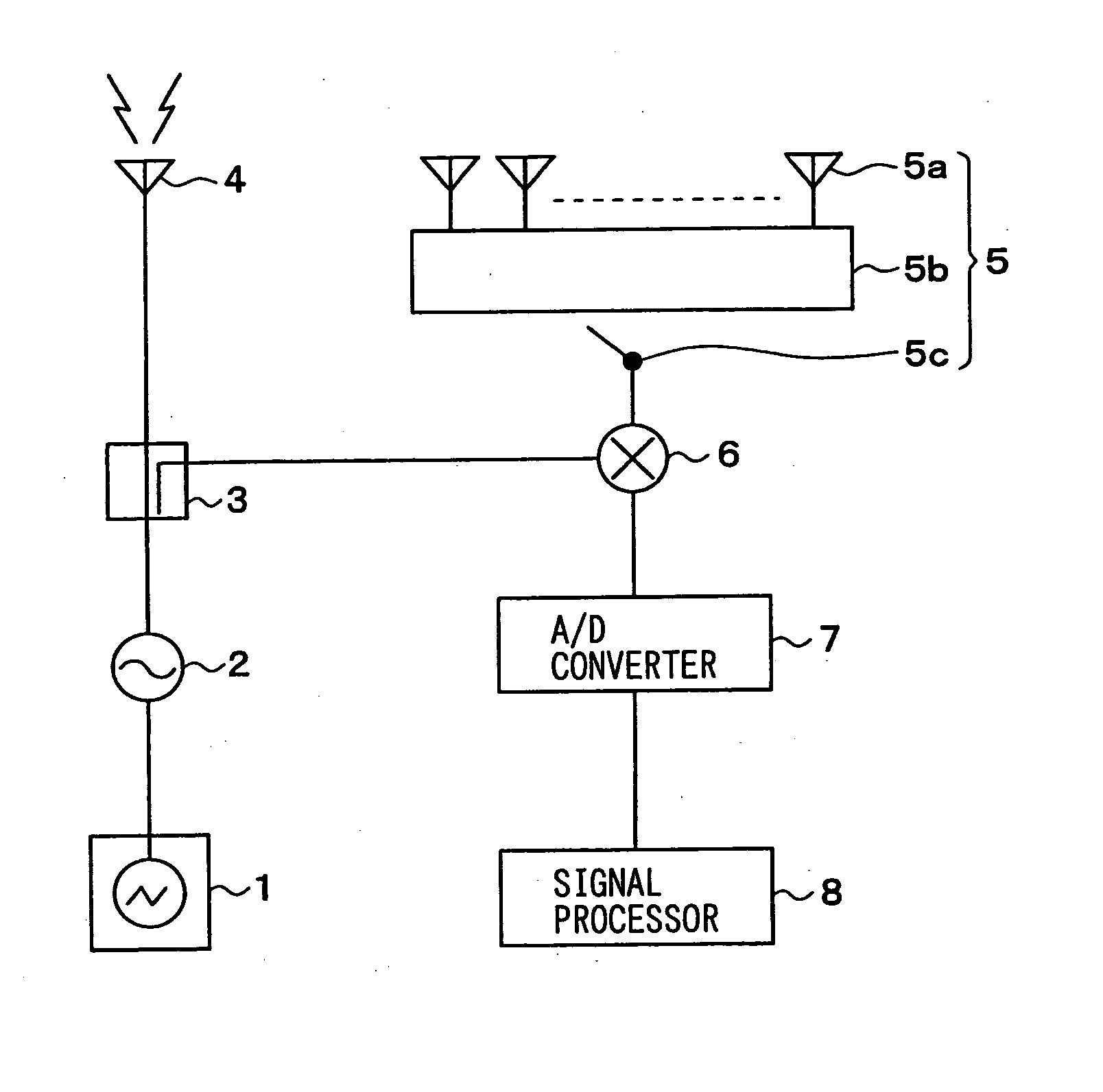
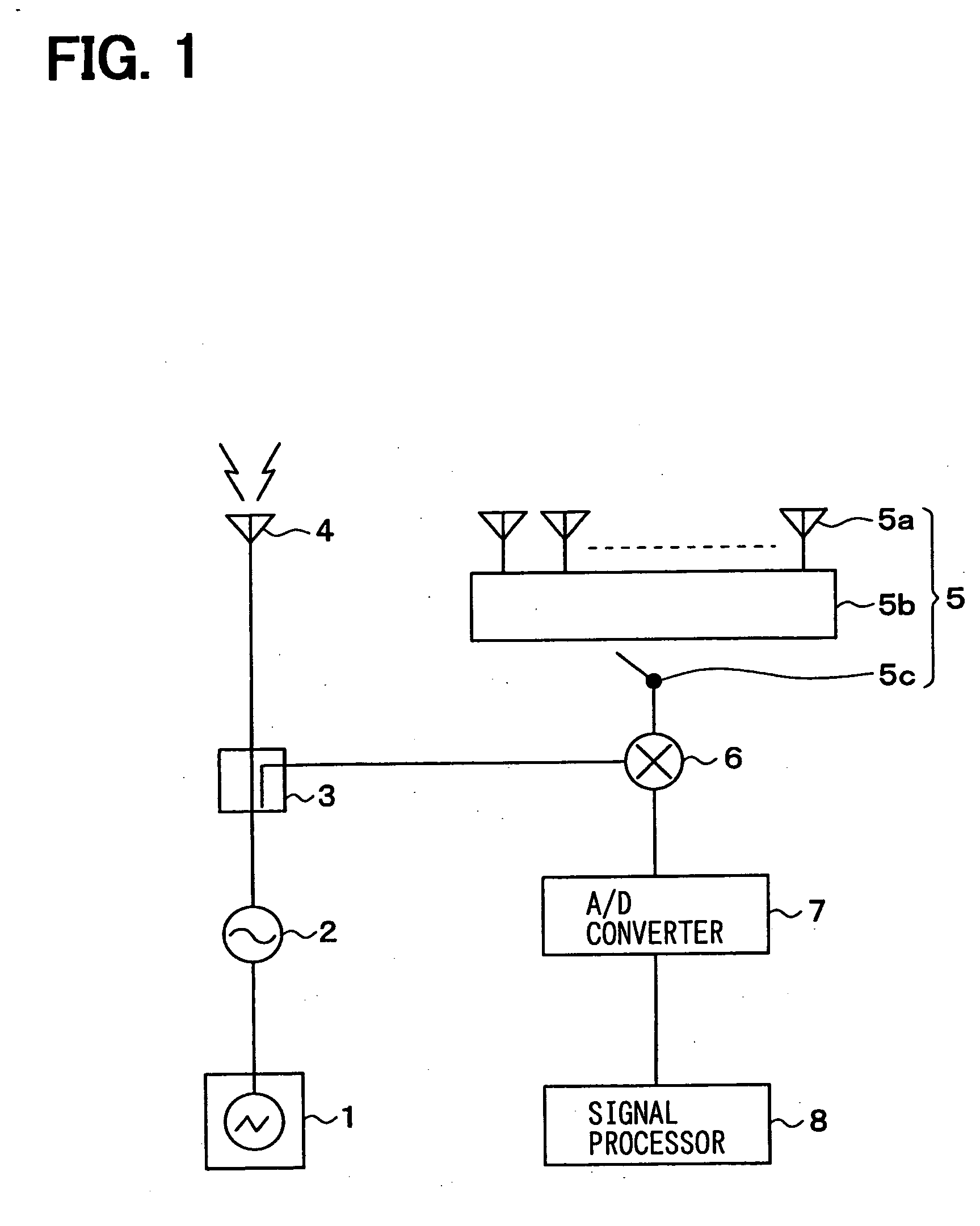
[0043] A first embodiment of the present invention, i.e., a radar device for an automotive use, is shown as a block diagram in FIG. 1.

[0044] The radar device transmits a millimetric radio wave toward, for example, a front space of an automobile to detect an object in front of the automobile. The radar device receives an incoming wave reflected by the object to detect a distance and an angle of the object. The radar device estimates the number of the incoming wave and the angle of the wave to calculate a relative speed of the object in a course of detection.

[0045] The radar device includes a modulation signal generator 1, a voltage-controlled oscillator (VCO) 2, a distributor 3, a transmission antenna 4, a receiver 5, a mixer 6, an A / D converter 7 and a signal processor 8.

[0046] The modulation signal generator 1 generates, for example, a modulation signal that is characterized by a linear increase and decrease of frequency in a triangular shape. The modulation signal is outputted ...

second embodiment

[0067] A second embodiment of the present invention is described with reference to the drawings. In the second embodiment, the incoming wave estimation process executed by the signal processor 8 in the first embodiment is modified. The other process of the invention remains intact. Therefore, only the modified part is described.

[0068] In the present embodiment, a maximum number of the incoming waves is considered besides sifting the signal from the noise in the incoming wave estimation process. The maximum number is set according to a target detection area of the millimetric wave transmitted from the transmission antenna 4.

[0069]FIG. 5 shows an illustration of automobiles in a target detection area of a radar wave transmitted from a transmission antenna. In this figure, it is perceived that a distance from a subject automobile is a determining factor of the maximum number of automobiles running parallel in the target detection area of the radar device.

[0070] For example, no more ...

third embodiment

[0077] A third embodiment of the present invention is described with reference to the drawings. In the third embodiment, the incoming wave estimation process executed by the signal processor 8 in the first embodiment is modified. The other process of the invention remains intact. Therefore, only the modified part is described.

[0078] In the third embodiment, the history of detection data is utilized in the incoming wave estimation process for predicting the number of objects detected in a subsequent cycle in addition to determining the maximum number.

[0079]FIG. 7 shows an illustration of positions and movement of the automobiles relative to the subject automobile. In this case, one of the automobiles running in front of the subject automobile catches up with the other automobile in the subsequent cycle of detection.

[0080] In this example, two automobiles are recognized in deferent areas because the beat frequencies from the two automobiles are different. That is, the number of the...


PUM


Abstract

A radar device uses a transmission signal outputted from a transmission antenna and a reception signal as an incoming wave reflected from a target object through an arrangement of reception antennas for estimating an angle of the incoming wave. An incoming wave estimation process stores a threshold for each beat frequency of the beat signal, and distinguishes the incoming wave in a signal space from the incoming wave in a non-signal space using the threshold. The estimation process facilitates an accurate estimation of the incoming wave in MUSIC method, ESPRIT method or the like.

Description

CROSS REFERENCE TO RELATED APPLICATION [0001] This application is based on and claims the benefit of priority of Japanese Patent Application No. 2004-199327 filed on Jul. 6, 2004, and Japanese Patent Application No. 2005-155627 filed on May 27, 2005, the disclosure of which is incorporated herein by reference. FIELD OF THE INVENTION [0002] The present invention generally relates to a radar device for transmitting a frequency modulated radar wave to detect an object. BACKGROUND OF THE INVENTION [0003] In recent years, an FMCW (Frequency Modulated Continuous Wave) type radar device is used for detecting an object and measuring a distance (refer to U.S. Pat. No. Document 6,040,796). The radar device using a detecting method such as the FMCW method transmits a radar wave to detect, for example, a relative speed and / or a distance to a preceding vehicle. Frequency modulated radar wave used in this type of device is transmitted to determine how many objects exist in a detecting area and in...

Claims


Application Information

Patent Timeline
Patent Type & Authority Applications(United States)
IPC IPC(8): G01S13/00G01S13/58G01S13/931
CPCG01S3/74G01S13/34G01S2013/9321G01S2013/9375G01S13/931G01S2013/93271
Inventor NATSUME, KAZUMAMIYAKE, YASUYUKI
Owner DENSO CORP
Learn More