Transmit and receive system for a cable data service

Inactive Publication Date: 2006-01-12
DESAI BHAVESH N +6
View PDF2 Cites 30 Cited by
  • Summary
  • Abstract
  • Description
  • Claims
  • Application Information

AI Technical Summary

Benefits of technology

[0013] It has, in accordance with the present invention, been recognized that a third category of techniques exists which, in combination with protocols to be described hereinbelow, can be used to improve the peak rate. This category includes those techniques which utilize parallel transmission. Employing parallel transmission over conventional Data Over Cable Standard Interface Specification (DOCSIS) protocol channels has the advantage of allowing users of the DOCSIS protocol as well as users of the protocols described hereinbelow to simultaneously share the same channel. It has further been recognized in accordance with the present inventi

Problems solved by technology

One problem with this category of solutions, however, is that this places strenuous demands

Method used


Image

  • Transmit and receive system for a cable data service
  • Transmit and receive system for a cable data service
  • Transmit and receive system for a cable data service

Examples


Example

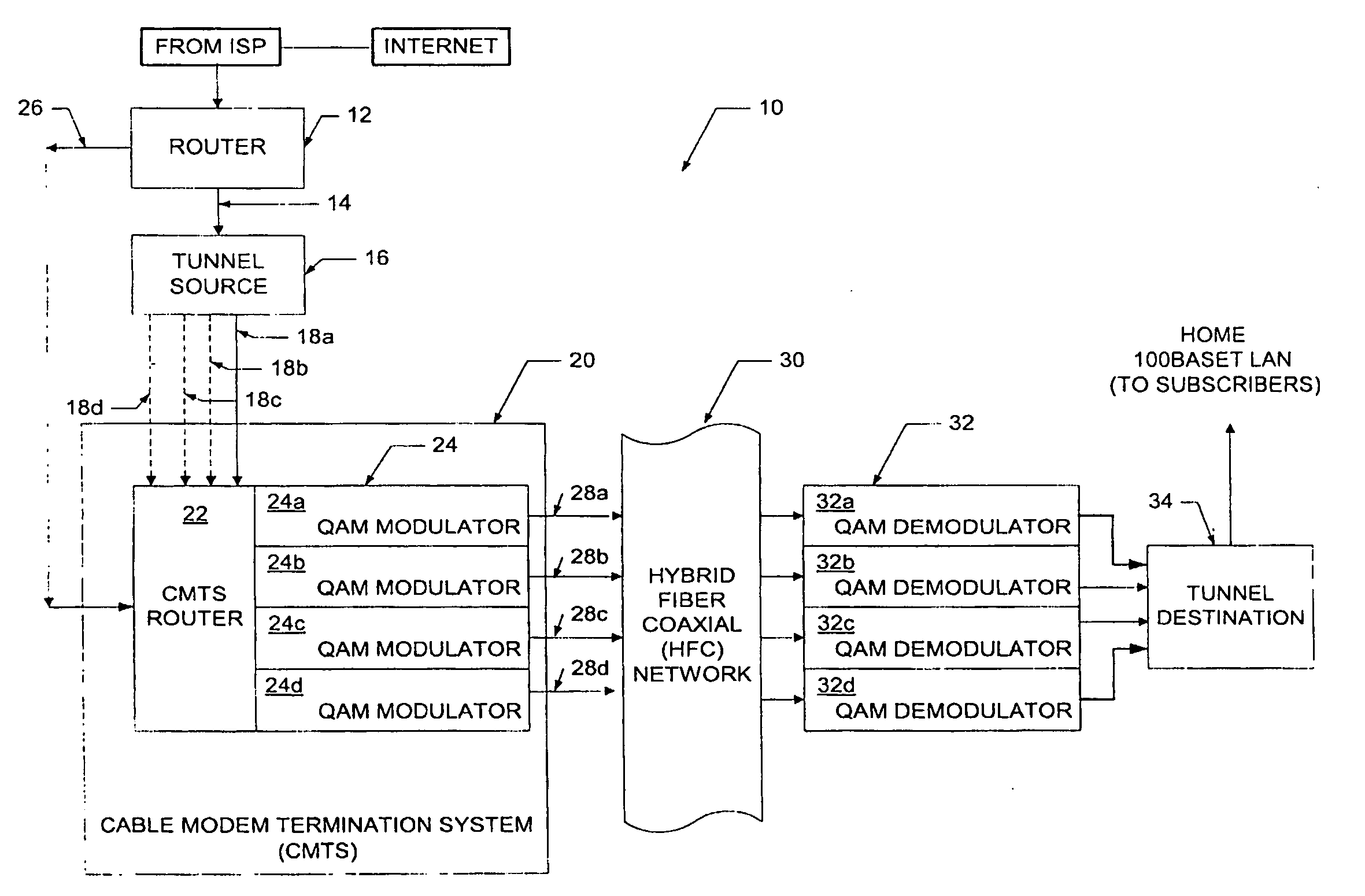
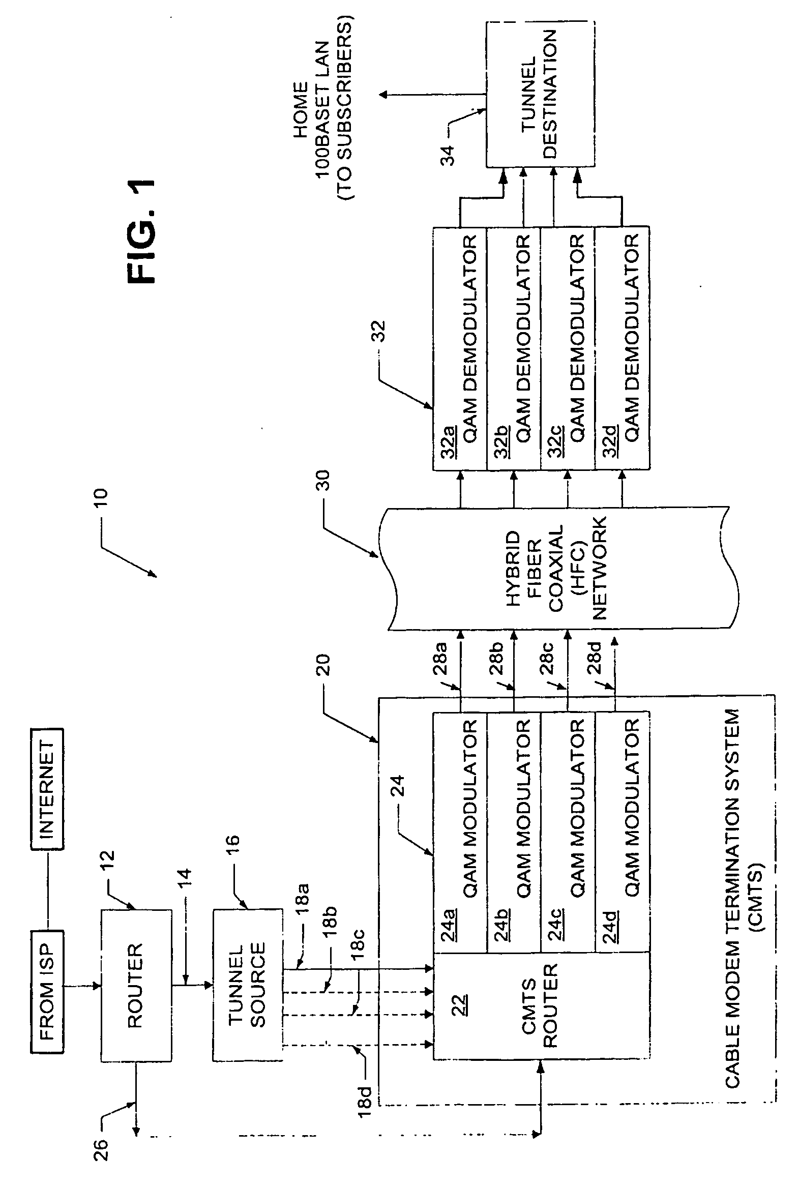
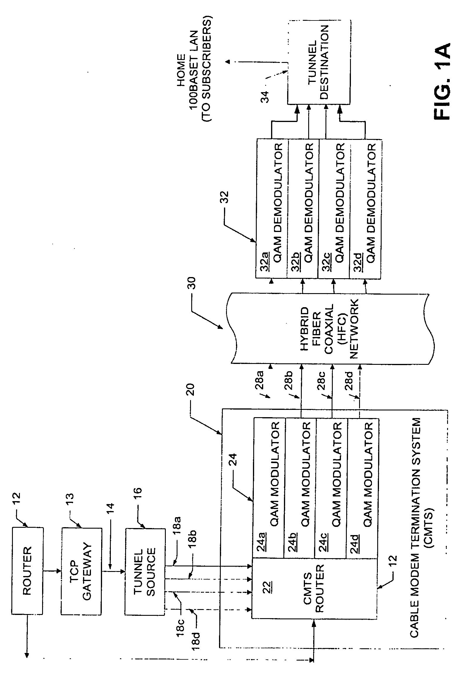
[0025] Referring now to FIG. 1, a downstream path of a transmission system 10 includes a first router 12 coupled to a tunnel source (also referred to as a sending tunnel end-point) 16 through a first signal path 14 (referred to hereinbelow as a FastChannel path). Tunnel source 16 is coupled to a cable modem termination system (CMTS) 20 through a second signal path 18 here shown as signal paths 18a-18d. It should be appreciated that the tunnel source 16 can functionally reside in a separate box upstream of the CMTS 20 as shown in FIG. 1. Alternatively, however, the tunnel source 16 can functionally reside within the CMTS 20 or the router 12.

[0026] The CMTS 20 includes a CMTS router 22 and a plurality of quadrature amplitude modulators (QAMs) 24a-24d generally denoted 24. Router 12 is also coupled to the CMTS 20, and in particular to the CMTS router 22, via a signal path 26. The purpose of the signal paths 14 and 26 will next be described in general overview.

[0027] In the system of ...


PUM


Abstract

A transmit and receive system for transmitting data between a transmit site and a receive site. The system includes a tunnel source, router and modulator for dividing a transmit data stream having a first bit rate into multiple data streams with each of the multiple data streams having a bit rate which is lower than the first bit rate, transmitting each of the multiple data streams over a plurality of RF channels. The system further includes a demodulator and destination source for recombining the multiple data streams at the receive site to provide a receive data stream having a bit rate equal to the first bit rate.

Description

RELATED APPLICATIONS [0001] This application is a continuation of application Ser. No. 09 / 924,617, which claims the benefit of U.S. Provisional Application No. 60 / 275,665 filed Mar. 14, 2001 which applications are hereby incorporated herein by reference in their entirety.FIELD OF THE INVENTION [0002] This invention relates generally to a data service and related apparatus and more particularly to a cable data service and system. BACKGROUND OF THE INVENTION [0003] As is known in the art, in addition to the transmission of television signals, it has been recognized that a cable network can also be used to transmit other types of data between remote locations. Thus, the cable network of the cable industry may be used as an alternative to communicating data via conventional telephone networks, such as the public switched telephone network (PSTN) for example. [0004] In this regard, cable networks are currently being used to transmit data to and from subscribers located at remote location...

Claims


Application Information

Patent Timeline
IPC IPC(8): H04L12/28H04L25/14H04L29/06
CPCH04L12/2801H04L12/2856H04L12/2861H04L69/14H04L25/14H04L29/06H04L12/2898H04L9/40
Inventor DESAI, BHAVESH N.SHANKARANARAYANAN, NEMMARA K.SHUR, DAVID HILTONSMILJANIC, ALEKSANDRATOTLAND, TODD J.VAN DER MERWE, JACOBUS E.WOODWARD, SHERYL LEIGH
Owner DESAI BHAVESH N
Why Eureka
Try Eureka