Screw compressor

a compressor and screw technology, applied in the direction of liquid fuel engines, machines/engines, rotary piston liquid engines, etc., can solve the problems of poor slow operation of the slide valve, and limit in many cases of increasing the diameter of the piston, so as to improve the responsivity in volume control and operate quickly

Active Publication Date: 2006-01-12
KOBE STEEL LTD
View PDF7 Cites 32 Cited by
  • Summary
  • Abstract
  • Description
  • Claims
  • Application Information

AI Technical Summary

Benefits of technology

[0009] In the screw compressor according to the present invention, the slide valve can be operated quickly and its responsivity in volume co

Problems solved by technology

However, in case of the slide valve being actuated by an ordinary type of a hydraulic cylinder and in case of the hydraulic cylinder being a single hydraulic cylinder, the operation of the slide valve becomes slow and the responsivity in operation, i.e., the responsivity in volume control, of the

Method used


Image

  • Screw compressor
  • Screw compressor
  • Screw compressor

Examples


Embodiment Construction

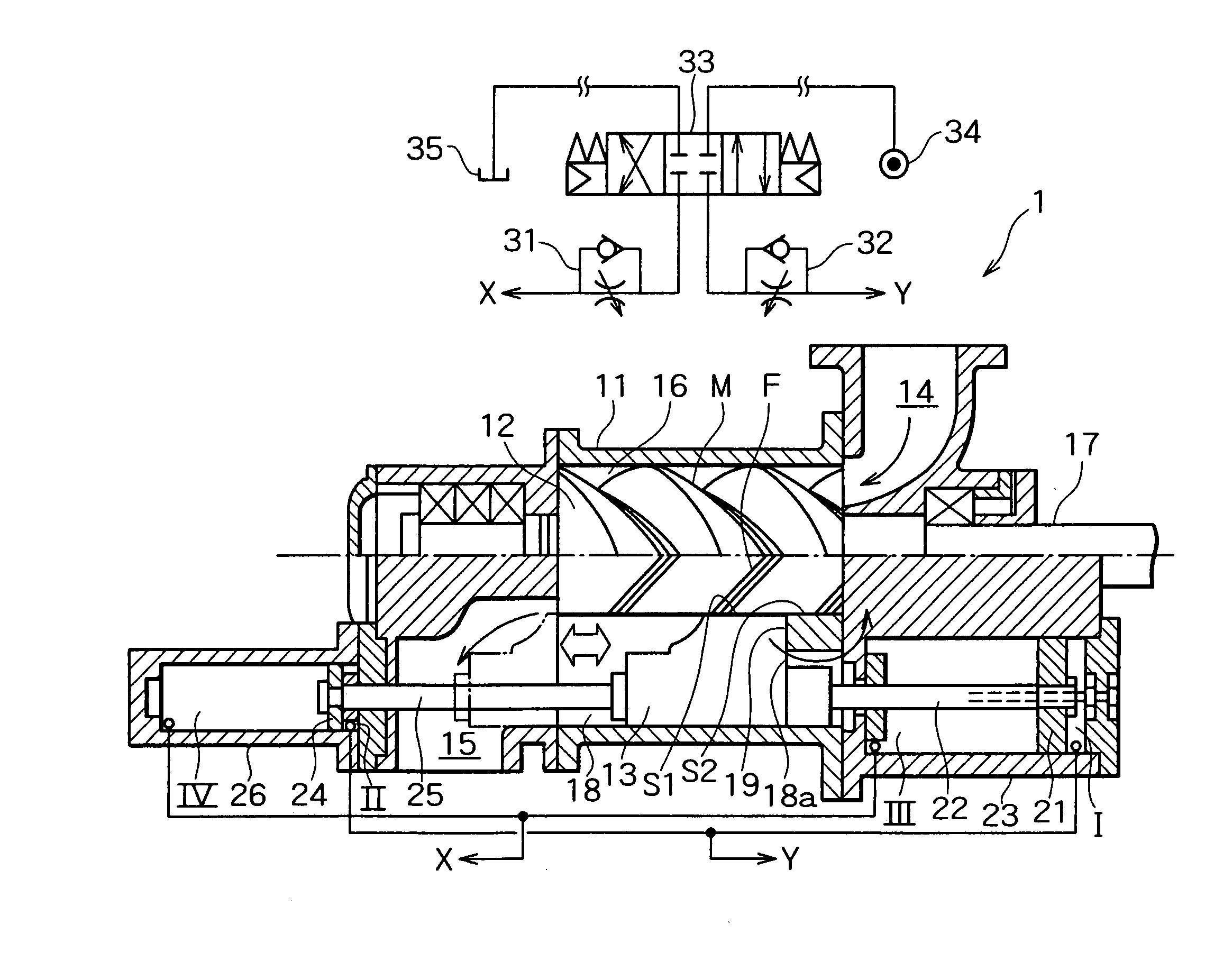
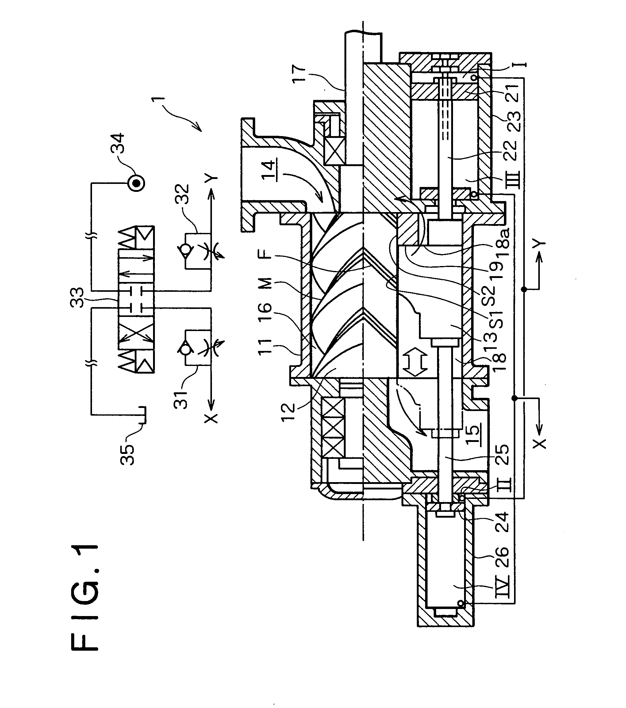
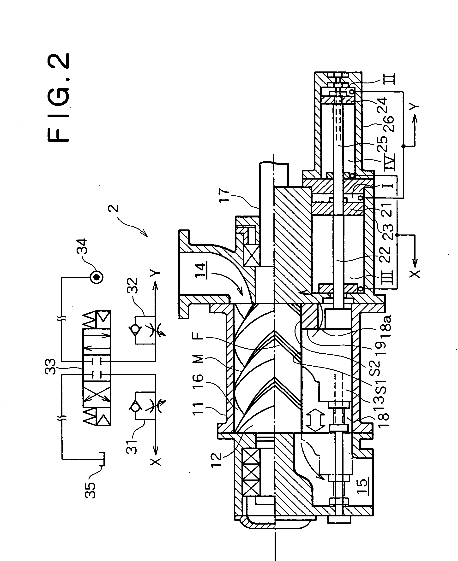
[0012] Embodiments of the present invention will be described in detail hereinunder with reference to the accompanying drawings. FIG. 1 shows a screw compressor 1 according to an embodiment of the present invention.

[0013] The screw compressor 1 includes a pair of female and male screw rotors 12, i.e., a female rotor F and a male rotor M, accommodated rotatably within a casing 11 and meshing with each other. The screw compressor 1 further includes a slide valve 13 in parallel with the axes of the screw rotors 12. The slide valve 13 is accommodated in the interior of the casing 11 in such a manner that the axis of the slide valve 13 is parallel to the axes of the screw rotors 12. With such a configuration, the slide valve 13 can move forward and backward in directions parallel to the axes of the screw rotors 12.

[0014] A suction port 14 is formed on one side of the casing 11, a discharge port 15 is formed on the other side of the casing 11, and a rotor chamber 16 is formed between th...


PUM


Abstract

A screw compressor according to the present invention includes a slide valve adapted to move forward and backward in parallel with the axis of a pair of screw rotors and also includes a plurality of hydraulic cylinders for moving the slide valve forward and backward, the plural hydraulic cylinders imparting, in synchronization with each other, a driving force to the slide valve in the same direction. With this configuration, it is possible to quicken an operation of the slide valve and improve the responsivity in volume control without increasing the diameters of pistons of the hydraulic cylinders for actuating the slide valve and without complicating equipment.

Description

BACKGROUND OF THE INVENTION [0001] 1. Field of the Invention [0002] The present invention relates to a screw compressor having a slide valve for adjusting a volume of discharged gas. [0003] 2. Description of the Related Art [0004] A screw compressor having a slide valve to adjust the volume of discharged gas has heretofore been known publicly. [0005] It is preferable for the slide valve to be superior in its operation responsivity so that the screw compressor can discharge compressed gas without excess or deficiency in the amount of the gas required in accordance with a change in the amount of consumption of the compressed gas discharged. However, in case of the slide valve being actuated by an ordinary type of a hydraulic cylinder and in case of the hydraulic cylinder being a single hydraulic cylinder, the operation of the slide valve becomes slow and the responsivity in operation, i.e., the responsivity in volume control, of the slide valve is poor. [0006] For improving the respon...

Claims


Application Information

Patent Timeline
IPC IPC(8): F01C1/16F01C1/24F03C2/00
CPCF04C28/125F04C18/16
Inventor HASEGAWA, MASATAKA
Owner KOBE STEEL LTD
Why Eureka
Try Eureka