Fuel cell system internal to portable computer

a fuel cell and portable technology, applied in the field of portable fuel cell storage devices, can solve the problems of reducing the practicality of portable fuel, burdensome storage and transportation of liquid hydrogen, and low energy density of gaseous hydrogen, and achieve the effect of facilitating hydrogen production

Inactive Publication Date: 2006-01-12
ULTRACELL LLC
View PDF98 Cites 45 Cited by
  • Summary
  • Abstract
  • Description
  • Claims
  • Application Information

AI Technical Summary

Benefits of technology

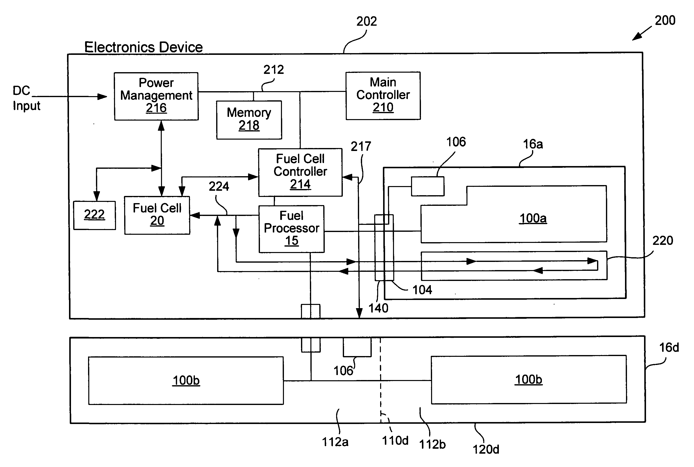
[0009] Hot swappable fuel storage systems described herein allow a portable hydrogen fuel source storage device to be removed from a fuel processor or electronics device it provides the hydrogen fuel source to, without shutting down the receiving device or without compromising hydrogen fuel source provision to the receiving device for a limited time. The hot swappable system comprises a reserve that provides the hydrogen fuel source to the receiving device. The reserve includes a volume that stores the hydrogen fuel source when the connector and mating connector are separated.
[0012] In yet another aspect, the present invention relates to a hot swappable fuel storage system. The hot swappable system comprises a hydrogen fuel source storage device. The storage device includes a) a bladder that contains the hydrogen fuel source and conforms to the volume of the hydrogen fuel source in the bladder, b) a housing that provides mechanical protection for the bladder; and c) a connector. The hot swappable system also comprises a mating connector that interfaces with the connector to permit transfer of the hydrogen fuel source between the storage device and a device that includes the mating connector. The hot swappable system further comprises a fuel processor that includes a reformer configured to receive the hydrogen fuel source from the mating connector, configured to output hydrogen, and including a catalyst that facilitates the production of hydrogen. The hot swappable system additionally comprises a hot swappable reserve configured to store the hydrogen fuel source when the connector and mating connector are separated.
[0014] In another aspect, the present invention relates to a fuel cell system for producing electrical energy. The fuel cell system comprises a hydrogen fuel source storage device for storing a hydrogen fuel source. The storage device includes a bladder that contains the hydrogen fuel source and conforms to the volume of the hydrogen fuel source in the bladder. The storage device also includes a housing that provides mechanical protection for the bladder. The storage device further includes a memory that stores information relevant to usage of the storage device. The storage device additionally includes a connector that interfaces with a mating connector to permit transfer of the hydrogen fuel source between the bladder and a device that includes the mating connector. The fuel cell system also comprises a fuel processor. The fuel processor includes a reformer configured to receive the hydrogen fuel source from the mating connector, configured to output hydrogen, and including a catalyst that facilitates the production of hydrogen. The fuel processor also includes a burner configured to provide heat to the reformer. The fuel cell system also comprises a fuel cell including a fuel cell stack configured to produce electrical energy using hydrogen output by the fuel processor.

Problems solved by technology

Gaseous hydrogen has a low energy density that reduces its practicality as a portable fuel.
Liquid hydrogen, which has a suitable energy density, must be stored at extremely low temperatures and high pressures, making storing and transporting liquid hydrogen burdensome.
Portable fuel source storage devices that service portable electronics such as laptop computers would be desirable but are not yet commercially available.

Method used


Image

  • Fuel cell system internal to portable computer
  • Fuel cell system internal to portable computer
  • Fuel cell system internal to portable computer

Examples


Embodiment Construction

[0027] The present invention is described in detail with reference to a few preferred embodiments as illustrated in the accompanying drawings. In the following description, numerous specific details are set forth in order to provide a thorough understanding of the present invention. It will be apparent, however, to one skilled in the art, that the present invention may be practiced without some or all of these specific details. In other instances, well known process steps and / or structures have not been described in detail in order to not unnecessarily obscure the present invention.

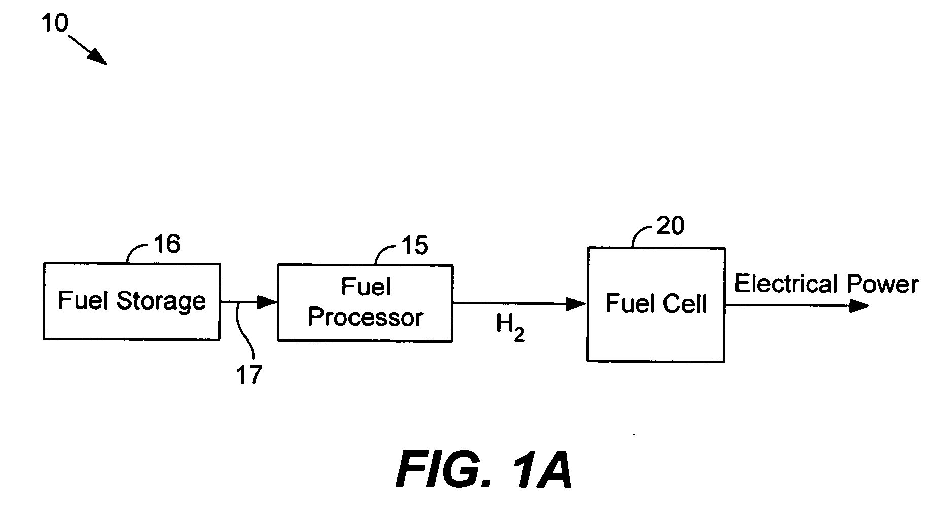
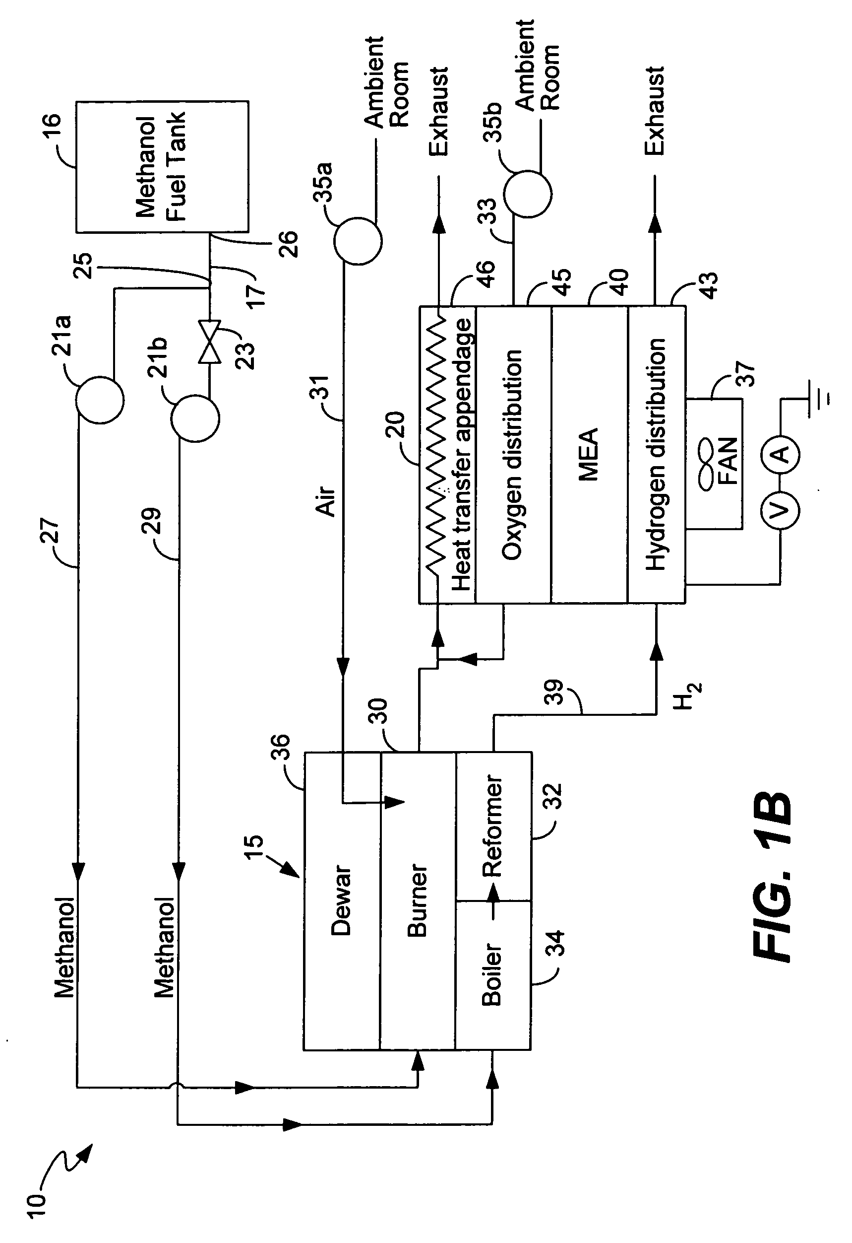
[0028]FIG. 1A illustrates a fuel cell system 10 for producing electrical energy in accordance with one embodiment of the present invention. Fuel cell system 10 comprises storage device 16, fuel processor 15 and fuel cell 20.

[0029] Storage device 16 and fuel processor 15 provide hydrogen to fuel cell 20. Storage device 16 and fuel processor 15 collectively act as a ‘reformed’ hydrogen supply that process...


PUM

PropertyMeasurementUnit
poweraaaaaaaaaa
temperatureaaaaaaaaaa
volumesaaaaaaaaaa

Abstract

Described herein is a portable storage device that stores a hydrogen fuel source. The storage device includes a bladder that contains the hydrogen fuel source and conforms to the volume of the hydrogen fuel source. A housing provides mechanical protection for the bladder. The storage device also includes a connector that interfaces with a mating connector to permit transfer of the fuel source between the bladder and a device that includes the mating connector. The device may be a portable electronics device such as a laptop computer. Refillable hydrogen fuel source storage devices and systems are also described. Hot swappable fuel storage systems described herein allow a portable hydrogen fuel source storage device to be removed from a fuel processor or electronics device it provides the hydrogen fuel source to, without shutting down the receiving device or without compromising hydrogen fuel source provision.

Description

CROSS-REFERENCE TO RELATED APPLICATIONS [0001] This application claims priority under U.S.C. §120 from co-pending U.S. patent application Ser. No. 10 / 877,766, filed Jun. 25, 2004 and entitled, “PORTABLE FUEL CARTRIDGE FOR FUEL CELLS”, which is incorporated herein for all purposes and which claims priority under 35 U.S.C. §119(e) from: a) U.S. Provisional Patent Application No. 60 / 482,996 filed Jun. 27, 2003 and entitled “Fuel cell system startup procedure and self-heating apparatus”, which is incorporated by reference for all purposes; b) U.S. Provisional Patent Application No. 60 / 483,415 filed Jun. 27, 2003 and entitled “Refillable Smart Methanol Cartridge for Fuel Cells”, which is incorporated by reference for all purposes; and c) U.S. Provisional Patent Application No. 60 / 483,416 filed Jun. 27, 2003 and entitled “Fuel Preheat in Portable Electronics Powered by Fuel Cells”, which is incorporated by reference for all purposes.BACKGROUND OF THE INVENTION [0002] The present invention...

Claims


Application Information

Patent Timeline
Patent Type & Authority Applications(United States)
IPC IPC(8): H01M8/06H01M8/04H05K5/00B65B1/04B65D85/00C08F4/636C08F4/649C08F4/651C08F4/654H01M
CPCF17C3/00Y02E60/50F17C2201/0157F17C2201/0166F17C2201/018F17C2201/019F17C2201/0195F17C2201/058F17C2203/0636F17C2203/0646F17C2203/066F17C2203/0663F17C2203/0697F17C2205/0332F17C2205/0341F17C2205/037F17C2205/054F17C2205/055F17C2205/057F17C2205/058F17C2221/033F17C2221/035F17C2223/0153F17C2223/033F17C2227/0128F17C2250/032F17C2250/036F17C2260/028F17C2260/036F17C2260/056F17C2270/0763H01M8/04014H01M8/04022H01M8/04186H01M8/04201H01M8/04208H01M8/04626H01M8/04686H01M8/04776H01M8/04917H01M8/0618H01M16/006H01M2008/1095H01M2250/30Y02B90/18Y02E60/321F17C2201/0128Y02B90/10Y02E60/10Y02E60/32
Inventor KAYE, IAN W.KASCHMITTER, JAMES L.
Owner ULTRACELL LLC
Why Eureka
Try Eureka