Intraluminal medical device having asymetrical members

a technology of asymetrical members and medical devices, which is applied in the field of expandable intraluminal medical devices, can solve the problems of stiffer stents, high experienced loading of radial arc members compared to the rest of the structure, and strain experienced by each member under load

Inactive Publication Date: 2006-01-12
BURGERMEISTER ROBERT +5
View PDF29 Cites 16 Cited by
  • Summary
  • Abstract
  • Description
  • Claims
  • Application Information

AI Technical Summary

Benefits of technology

[0018] Still another medical device according to the present invention comprises a stent including one or more flex connectors having at least one flex component. The flex component has non-uniform cross-sections to achieve near-uniform stress distribution along the flex component when the flex component undergoes deformation.
[0019] The present invention also contemplates a stent having one or more radial support members, including at least one radial component. The radial component has non-uniform cross-sections to achieve near-uniform stress distribution along the radial component when the radial component undergoes deformation.
[0020] Another stent according to the present invention comprises one or more members each having at least one component. The component has non-uniform cross-sections to achieve near-uniform stress distribution along the component when the component undergoes deformation.
[0021] Still another stent according to the present invention includes a plurality of hoop components having a tubular configuration with proximal and distal open ends defining a longitudinal axis extending there between. Each hoop component is formed as a continuous series of substantially longitudinally oriented radial strut members and a plurality of radial arc members connecting adjacent radial struts. At least one radial arc member has non-uniform cross-sections to achieve near-uniform stress distribution along the radial arc when the radial undergoes deformation. The stent further comprises one or more longitudinally oriented flex connectors connecting adjacent hoop components. Each flex connector comprising flexible struts, with each flexible strut being connected at each end by one flexible arc.
[0022] Still another stent according to the present invention comprises one or more hoop components having a tubular configuration with proximal and distal open ends defining a longitudinal axis extending there between. Each hoop component is formed as a continuous series of substantially longitudinally oriented radial strut members and a plurality of radial arc members connecting adjacent radial struts. At least one radial arc member has a non-uniform profile to achieve near-uniform strain distribution along the radial arc when the radial arc undergoes deformation.
[0023] The present invention also contemplates a stent having one or more flexible connectors connecting adjacent hoop components. Each flexible connector is formed as a continuous series of substantially longitudinally oriented flexible strut members and a plurality of flexible arc members connecting adjacent flexible struts. At least one flexible arc member has a tapered profile to achieve near-uniform strain distribution along the flexible arc when the flexible arc undergoes deformation.

Problems solved by technology

Although the geometry of the stent members may be uniform, the strain experienced by each member under load is not.
In particular, the radial arc members are high in experienced loading compared to the remainder of the structure.
Accordingly, when a stent has members with a generally uniform cross-section, some stent members will be over designed in regions of lesser induced strain, which invariably results in a stiffer stent.
High stress and / or strain can cause cracking of the metal and potential fatigue failure of the stent under the cyclic stress of a beating heart.
This traditional stress / strain-life approach to fatigue analysis, however, only considers geometry changes that are uniform in nature in order to achieve an acceptable stress and / or strain state, and does not consider optimization of shape to achieve near uniform stress and / or strain along the structural member.
In addition, the presence of flaws in the structure or the effect of the propagation of such flaws on stent life are usually not considered.
Moreover, optimization of the geometry considering flaws in the stent structure or the effect of the propagation of such flaws has not been implemented.

Method used


Image

  • Intraluminal medical device having asymetrical members
  • Intraluminal medical device having asymetrical members
  • Intraluminal medical device having asymetrical members

Examples


Embodiment Construction

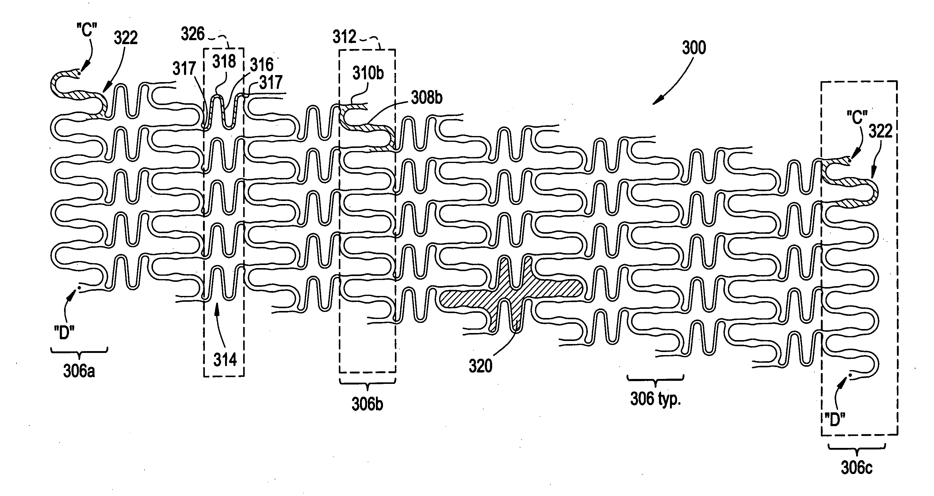
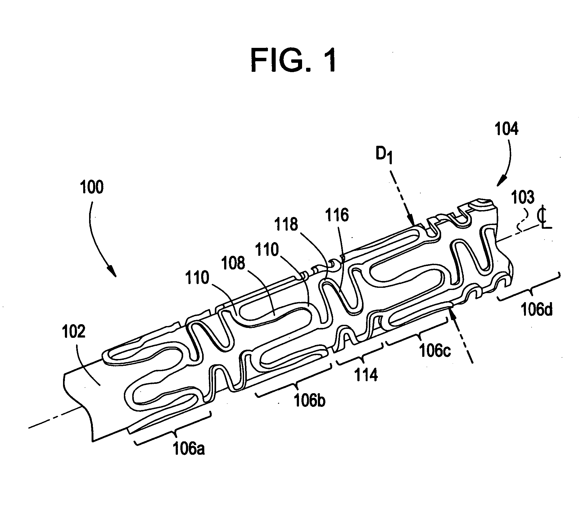
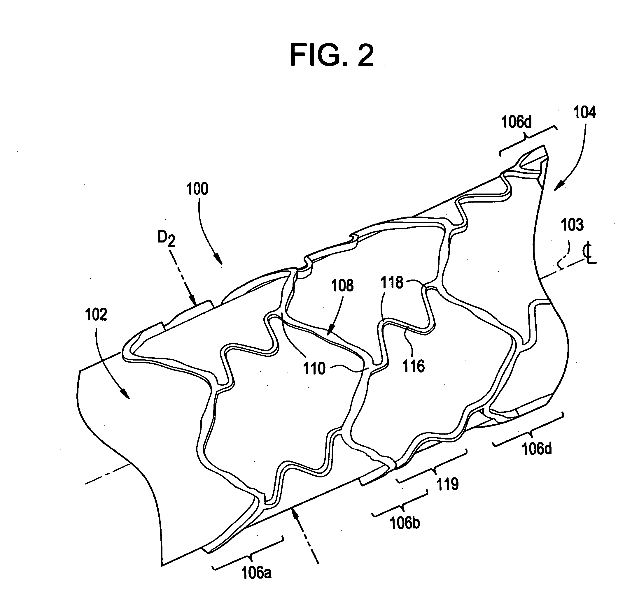
[0037] The present invention describes an intraluminal medical device that is capable of expanding into the wall of a vessel lumen and physiological loading, while maintaining near uniform stress (uniform fatigue safety factor) and / or strain in one or more of the device components during use. For the purpose of this description, “use” may include the delivery, deployment and post deployment (short and long term) state of the device. An intravascular stent will be described for the purpose of example. However, as the term is used herein, intraluminal medical device includes but is not limited to any expandable intravascular prosthesis, expandable intraluminal vascular graft, stent, or any other mechanical scaffolding device used to maintain or expand a body passageway. Further, in this regard, the term “body passageway” encompasses any duct within a mammalian's body, or any body vessel including but not limited to any vein, artery, duct, vessel, passageway, trachea, ureters, esophagu...


PUM


Abstract

This invention relates generally to expandable intraluminal medical devices for use within a body passageway or duct, and more particularly to an optimized stent having asymmetrical strut and loop members. In one embodiment of the invention the stent includes one or more members each having at least one component. The component has non-uniform cross-sections to achieve near-uniform stress distribution along the component when the component undergoes deformation.

Description

CROSS-REFERENCE TO RELATED APPLICATIONS [0001] This application claims priority pursuant to 35 U.S.C. § 119 (e) to provisional application 60 / 584,375 filed on Jun. 30, 2004.FIELD OF THE INVENTION [0002] This invention relates generally to expandable intraluminal medical devices for use within a body passageway or duct, and more particularly to an optimized stent having asymmetrical strut and loop members. BACKGROUND OF THE INVENTION [0003] The use of intraluminal prosthetic devices has been demonstrated to present an alternative to conventional vascular surgery. Intraluminal prosthetic devices are commonly used in the repair of aneurysms, as liners for vessels, or to provide mechanical support and prevent the collapse of stenosed or occluded vessels. [0004] Intraluminal endovascular prosthetics involve the percutaneous insertion of a generally tubular prosthetic device, such as a stent, into a vessel or other tubular structure within the vascular system. The stent is typically deliv...

Claims


Application Information

Patent Timeline
Patent Type & Authority Applications(United States)
IPC IPC(8): A61F2/06
CPCA61F2/91A61F2/915A61F2002/91533A61F2230/0013A61F2250/0029A61F2250/0036A61F2002/91558
Inventor BURGERMEISTER, ROBERTDUERIG, THOMASGRISHABER, RANDYMARREY, RAMESHPARK, JINKREVER, MATHEW
Owner BURGERMEISTER ROBERT
Why Eureka
Try Eureka