Method, computer program product and data structure for representing two- or three-dimensional object modeling

a two-dimensional object and data structure technology, applied in the direction of roads, instruments, traffic restrictions, etc., can solve the problems of difficult to bring data for interface between the planar and curved surfaces that are difficult to be consistent with each other, and achieve the effect of reducing the storage requiremen

Inactive Publication Date: 2006-01-12
FURUKAWA SUSUMU +1
View PDF35 Cites 6 Cited by
  • Summary
  • Abstract
  • Description
  • Claims
  • Application Information

AI Technical Summary

Benefits of technology

[0014] It is therefore an object of the present invention to provide a data structure enabling unified data manipulation that

Problems solved by technology

However, it is very troublesome to represent a graph of a three-dimensional solid object having planar and curved surfaces even by the half-edge data structure.
This is because planer and curved surfaces are represented in different data formats and, in consequence, it is hard pressed to bring data for interface between these planar and curved surfaces consistency with each other.
In addition, it is considerably time and energy-consuming to create a program, besides the program itself and data spend a huge storage space.
In such a system, the representation is not a physical solid model, an adverse consequence is encountered in the case of determining a tool path or rout for numerically controlled machine tools.
The data manipulation of a representation of a curved surface is an extremely intractable job.
Such a data structure encounters a decline in data processing efficiency and, in consequence, less utilized in CAD systems.
This fo

Method used


Image

  • Method, computer program product and data structure for representing two- or three-dimensional object modeling
  • Method, computer program product and data structure for representing two- or three-dimensional object modeling
  • Method, computer program product and data structure for representing two- or three-dimensional object modeling

Examples


Embodiment Construction

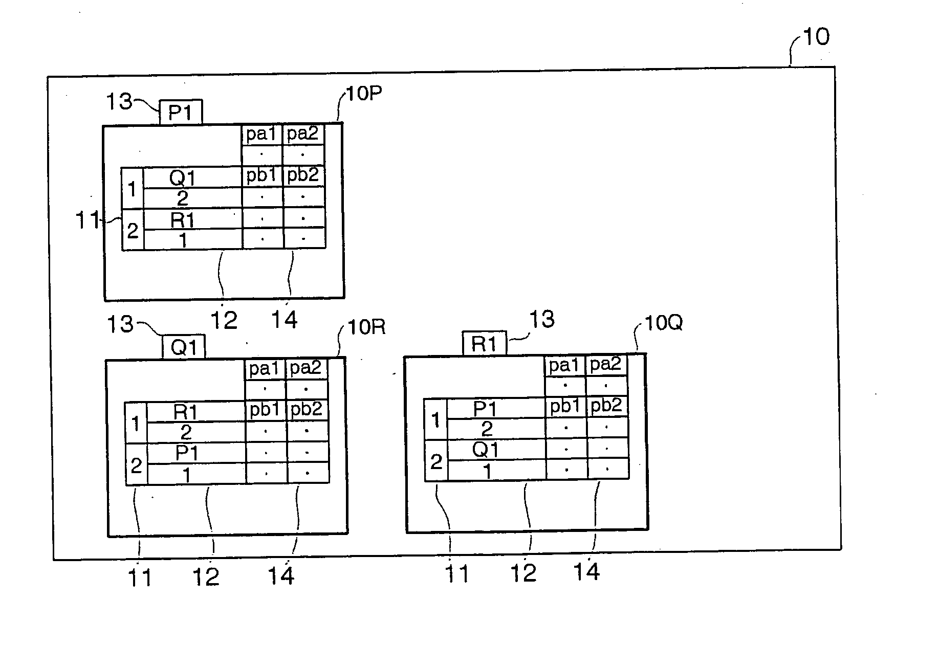
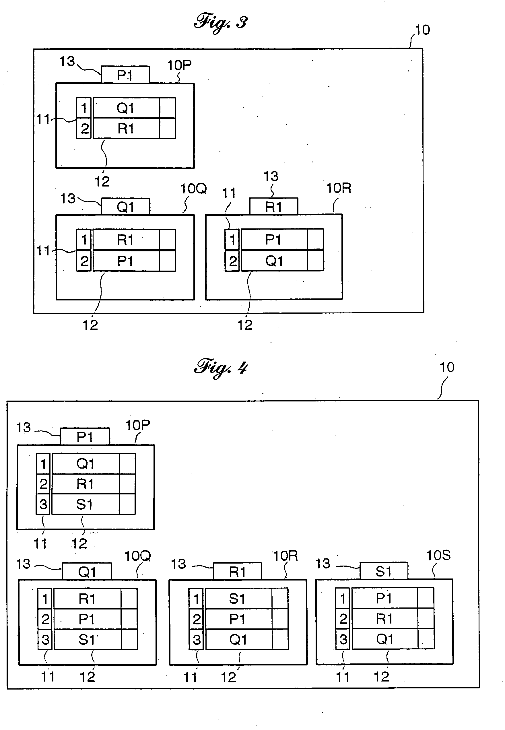
[0058] The term “constitutive point” as used herein shall mean and refer to each of the constitutive points by which a graph is defined. The term “adjacent point” as used herein shall mean and refer to one of endpoints of a line segment, a straight line or a curved line, relative to another endpoint of the line segment. In other words, opposite endpoints of a line segment are directly adjacent relatively to each other. The term “point data” of a constitutive point as used herein shall mean and refer to the data for a representation of topological and geometric information of constitutive point of a graph.

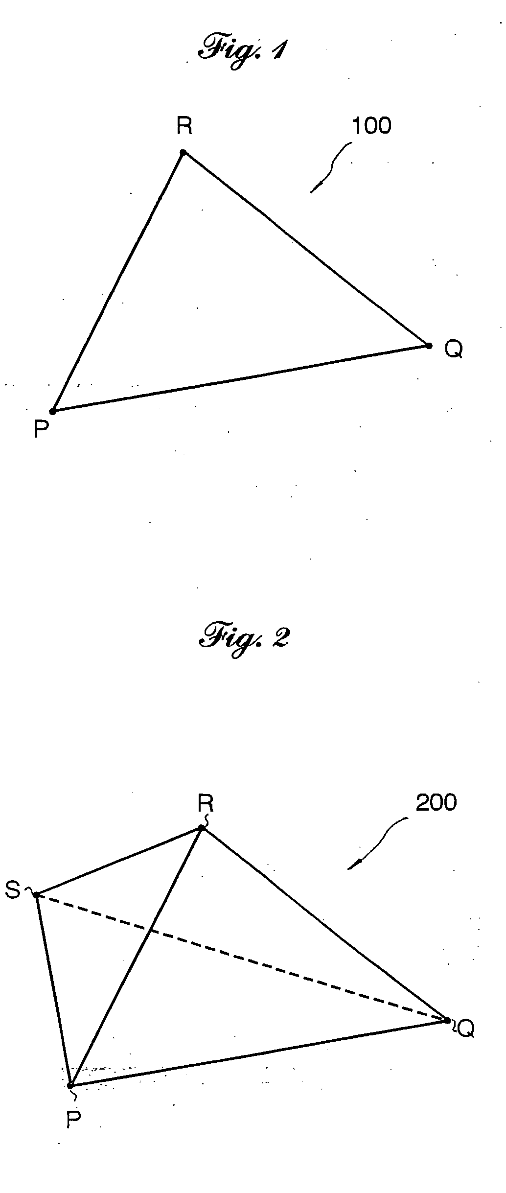
[0059] Referring to the accompanying drawings in detail, and, in particular, to FIGS. 1 and 2 illustrating an embedded graph representation of a polygonal or two-dimensional object (which is hereafter referred to as a graph for simplicity)100, namely a triangle PQR, and an embedded graph representation of a polyhedral or three-dimensional object (which is hereafter referred to as a...


PUM


Abstract

A data structure for a graph, which is composed by points and line segments connecting adjacent pairs of the points, respectively, of a two- or three-dimensional object comprises a set of point data of the individual points, each of the point data of the points consists of a clockwise or counter clockwise circular ordered adjacency list written in storage areas of a storage medium individually allocated to the point. The adjacency list describes a plurality of adjacent points associated with the point sequentially according to a circular adjacency order as viewed from outside of the graph with address pointers to the storage areas allocated to the adjacent points, respectively, and location pointers associated with the address pointers, respectively, to storage locations of adjacency lists of the adjacent points, respectively, where an address pointer of the point is written.

Description

BACKGROUND OF THE INVENTION [0001] 1. Field of the Invention [0002] The present invention relates to a method, a computer program product and a data structure for a representation of graphical information of a two- or three-dimensional object. [0003] 2. Description of Related Art [0004] In recent years, it plays a key role in various fields including design and production using computer-assisted design (CAD) system and / or computer-assisted manufacturing (CAM) system, environmental recognition techniques of robots, various scientific simulations, computer graphics, and the like to perform graphics data processing on a computer display image for two- or three-dimensional object modeling and to store the data representing the graphics information structured in a specific form on a storage medium capable of being accessed and read by a computer. In particular, there have been proposed, in the technical field of CAD / CAM system, a variety of data structures for storing and saving edited g...

Claims


Application Information

Patent Timeline
IPC IPC(8): G06F17/00G06T17/20
CPCG06T17/20E01F13/06G08G1/095
Inventor FURUKAWA, SUSUMUSHIMIZU, SEIJIMUKAI, SHINJIHARA, YUTAKAMONMA, HIROKOFUKUSHIMA, MAMORU
Owner FURUKAWA SUSUMU
Why Eureka
Try Eureka