Pressurized near-isothermal fuel cell - gas turbine hybrid system

a gas turbine hybrid and near-isothermal technology, applied in the field of hybrid systems, can solve the problems of affecting the structural integrity and reliability of the stack, the inability of the sofc stack to withstand a large thermal gradient or temperature rise, and the high airflow ra

Inactive Publication Date: 2006-01-19
GENERAL ELECTRIC CO
View PDF5 Cites 40 Cited by
  • Summary
  • Abstract
  • Description
  • Claims
  • Application Information

AI Technical Summary

Problems solved by technology

Usually, the cooling requirement imposed on the airflow results in a much higher airflow rate than that required for the fuel cell reaction due to the poor heat transfer characteristics of air and, equally importantly, the inability of the SOFC stack to withstand a large thermal gradient or temperature rise from stack inlet to stack exhaust due to thermal stresses.
The presence of large temperature gradients may be detrimental to both structural integrity and reliability of the stack.
If the temperature rise is too large, differential thermal expansion of various stack components (cell, interconnect, seals, etc.) can lead to cell fracture, loss of sealing, or loss of contact between stack components, thereby leading to stack failure.
In the absence of stack failure, stack service life is compromised due to the fact that cell component degradation is strongly temperature dependent.
Cell degradation is much faster in the high temperature region (typically near the exhaust) than in the low temperature region (typically near the inlet), thereby over time leading to reduced stack power or system efficiency, or both.
The power required for circulating this additional cooling airflow lowers the overall system efficiency.
Additionally, because the SOFC stack cannot withstand large temperature gradients, it is necessary to preheat the air to a temperature nearly equal to the stack temperature before it enters the stack.
This heat transfer process is also inefficient, resulting in some loss of system efficiency, and is also complicated and expensive due to the need to employ high temperature materials consistent with the high operating temperatures of SOFC stacks.
The former method suffers from reduced system efficiency at low pressure, while the latter employs an unreliable component, the high-temperature heat exchanger, which is subject to high thermal stresses and high material oxidation rates due to its exposure to high temperature.

Method used


Image

  • Pressurized near-isothermal fuel cell - gas turbine hybrid system
  • Pressurized near-isothermal fuel cell - gas turbine hybrid system
  • Pressurized near-isothermal fuel cell - gas turbine hybrid system

Examples


Embodiment Construction

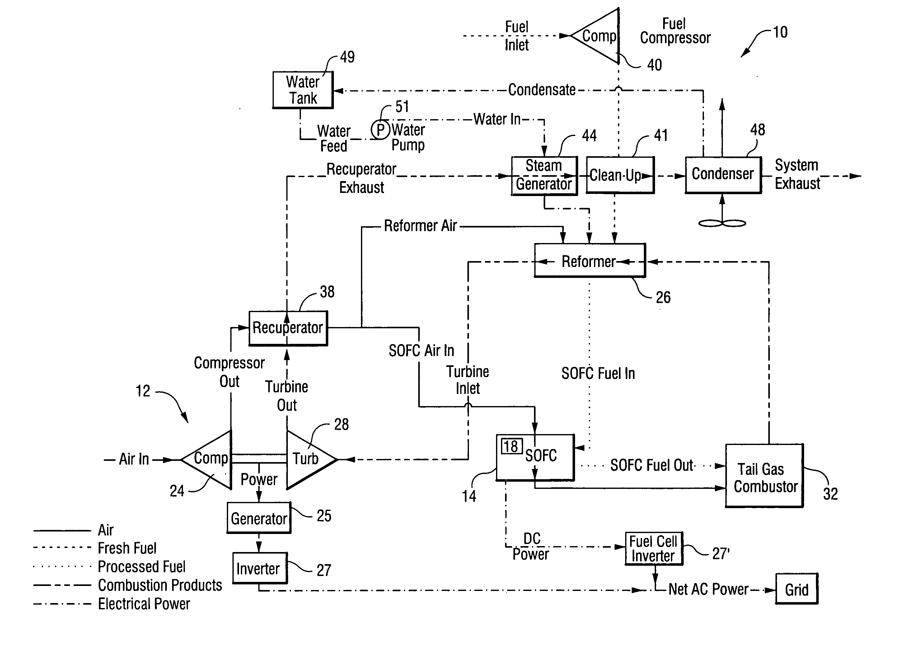
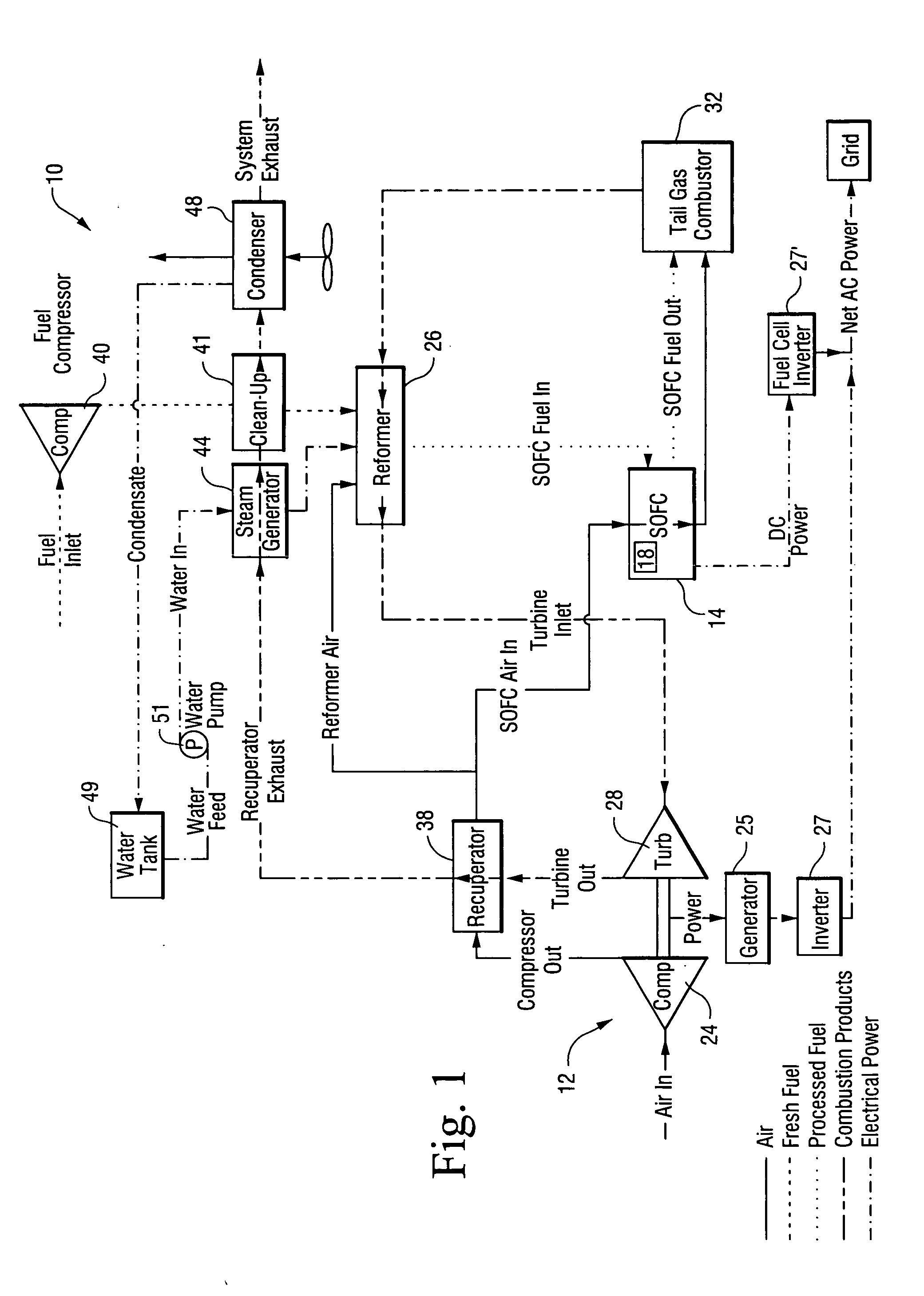
[0012] The system 10 will be described with reference to FIG. 1. Generally, the hybrid system 10 includes a turbine component 12 and a fuel cell component. The fuel cell component includes a fuel cell 14 having a plurality of power-producing electrode-electrolyte assemblies, flow distribution assemblies, and heat-conducting elements 18, such as heat pipes, which may or may not be connected to the flow distribution assemblies. As an alternative to heat pipes, high thermal conductance members may be used. The heat-conducting elements 18 have a high thermal conductance, which allows for an efficient transfer of fuel cell by-product heat to incoming reactants. The high thermal conductivity of the elements 18 allows for very small temperature gradients in the fuel cell, thus making the fuel cell nearly isothermal. In addition, the heat-conducting elements are typically good electrical current conductors and may serve as the fuel cell's interconnects that serve the purpose of transferring...


PUM

PropertyMeasurementUnit
temperatureaaaaaaaaaa

Abstract

A hybrid fuel cell-gas turbine system and method efficiently generates power using a combination of separate power generating components. The system includes a turbine system having an air compressor and a turbine, and a fuel cell. By-product waste heat from the fuel cell is used within the fuel cell to heat the cathode air.

Description

BACKGROUND OF THE INVENTION [0001] The present invention relates to a hybrid system combining a gas turbine (GT) or a micro-turbine (MT) with a near-isothermal high-temperature fuel cell, for example a solid oxide fuel cell (SOFC), to produce electrical power. [0002] Though very efficient power producers, fuel cells still generate much by-product heat that needs to be removed to avoid overheating the fuel cell. High-temperature fuel cells, such as the solid oxide fuel cell (SOFC), systems are normally designed so that the by-product heat is removed with airflow through the fuel cell. The air also serves as the reactant in the fuel cell cathode. Usually, the cooling requirement imposed on the airflow results in a much higher airflow rate than that required for the fuel cell reaction due to the poor heat transfer characteristics of air and, equally importantly, the inability of the SOFC stack to withstand a large thermal gradient or temperature rise from stack inlet to stack exhaust d...

Claims


Application Information

Patent Timeline
Patent Type & Authority Applications(United States)
IPC IPC(8): H01M8/00H01M8/04F03G6/00H01M8/12B60L8/00B60K16/00
CPCF02C6/10Y02E60/525H01M8/0223H01M8/0267H01M8/04022H01M8/04074H01M8/04111H01M8/0618H01M2008/1293H01M2250/402Y02B90/12Y02E10/46F05D2220/76F05D2210/10Y02E60/50F05D2250/82Y02B90/10Y02T10/7072H01M8/2483H01M8/2425H01M8/0258
Inventor REHG, TIMOTHY JOSEPHSOKOLOV, PAVEL ALEXANDROVICHFENGLER, WOLFGANG ALAN
Owner GENERAL ELECTRIC CO
Why Eureka
Try Eureka