Clutch release bearing and method of manufacture

a technology of hydraulic operation and bearings, which is applied in the direction of fluid-actuated clutches, clutches, non-mechanical actuated clutches, etc., can solve the problems of high cost of components and mounting, and the nature is likely to give rise to wear, so as to reduce and be particularly robust and reliable. , to achieve the effect of reducing the risk of deformation and creep

Inactive Publication Date: 2006-01-19
AB SKF
View PDF67 Cites 28 Cited by
  • Summary
  • Abstract
  • Description
  • Claims
  • Application Information

AI Technical Summary

Benefits of technology

[0023] This then provides the benefit of an associated piston and sealing assembly that is particularly robust and reliable while at the same time remaining economical. The injection-molding method is put to good use to form the pips which are normally considered to be unwanted sprue at the time of mold release. The piston and associated seal assembly may include just two components suitably angularly coupled to one another. It is also particularly advantageous to anticipate injecting the piston via the rear surface as this makes it possible to form sharp corners between the cylindrical surfaces of the piston and the rear surface of the piston at the mold closure. These sharp corners greatly reduce the risk of deformation and creep of the external and internal periphery of the seal, something which would occur if there were a rounded part of the piston near the cylinder, with the risk of that part of the seal that crept into the rounded portions rapidly becoming crushed and damaged as the piston moved and giving rise to a gradual impairment of the sealing.

Problems solved by technology

The cost of the component and of mounting it is high.
Even if these angular movements are of small amplitude, their repetitive nature is likely to give rise to wear that is detrimental to the sealing of the device—see, for example, document FR-A-2 668 560.

Method used


Image

  • Clutch release bearing and method of manufacture
  • Clutch release bearing and method of manufacture
  • Clutch release bearing and method of manufacture

Examples


Embodiment Construction

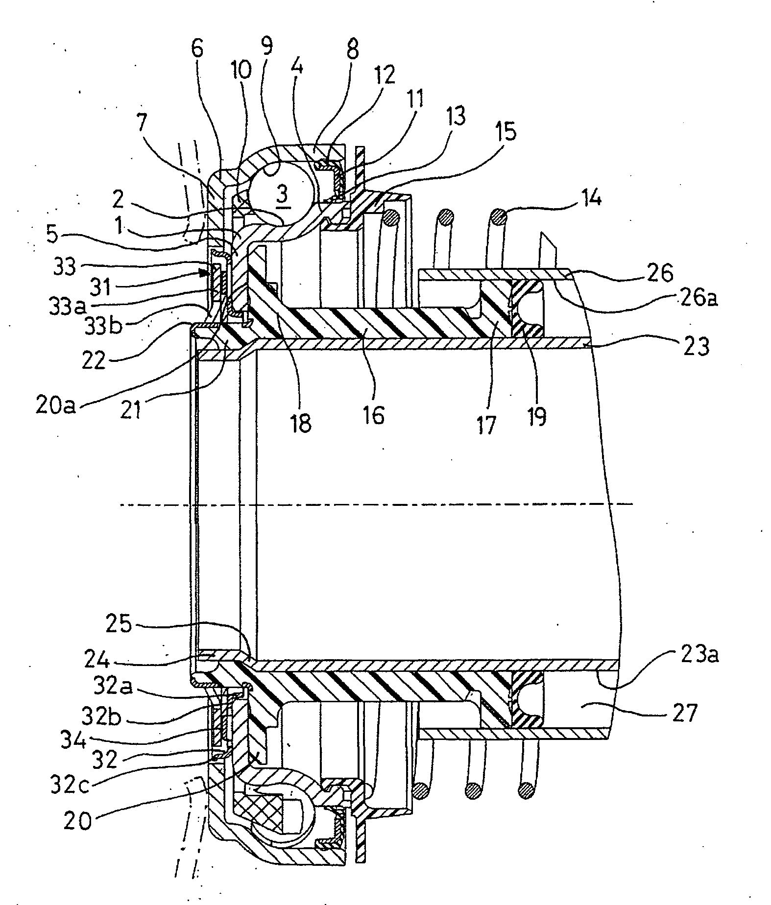
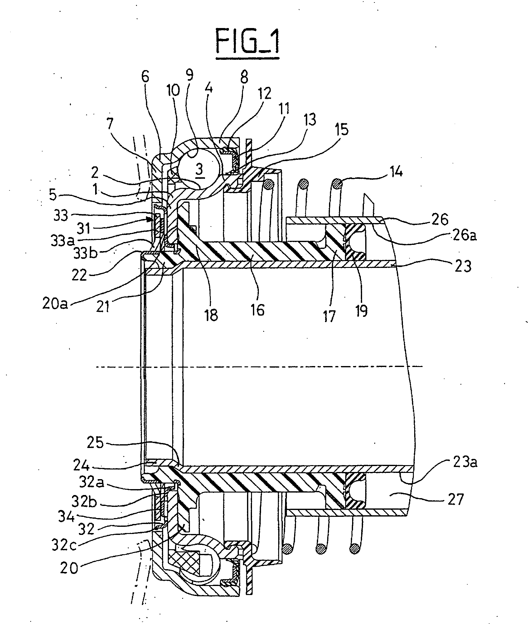
[0032] As can be seen in FIG. 1, the clutch release bearing includes a thin-walled rolling bearing non-rotating ring 1 made by pressing a metal sheet or a tube having a circular raceway in the form of a portion of torus 2 for a row of rolling elements, in this instance balls 3, the said raceway having a central axial cross section with a profile in the shape of a concave arc of a circle. The inner ring 1 includes an axial portion 4 and a radial portion 5 directed inwards, said portions 4 and 5 being arranged on each side of the rolling elements 3. The non-rotating ring 1 is an inner ring. As an alternative, the non-rotating ring 1 may be an outer ring.

[0033] The rolling-contact bearing is completed by an outer ring 6 having a radial portion 7 projecting towards the inside of the entity and a cylindrical portion 8 on the same side as the radial portion 4. The radial portion 7 is capable of coming into contact with the surface of a diaphragm or equivalent element, depicted in chain l...


PUM


Abstract

Hydraulically operated clutch release bearing device of the type including an operating element provided with an annular piston and a seal in contact with the piston, and a rolling-contact bearing axially secured to the operating element, the piston including a rear surface in contact with the said seal, at least one concave region being formed locally in the said rear surface of the piston.

Description

BACKGROUND OF THE INVENTION [0001] 1. Field of the Invention [0002] The present invention relates to the field of hydraulically operated clutch release bearings, particularly those intended to act on the diaphragm of a clutch, in particular for a motor vehicle. [0003] 2. Description of the Relevant Art [0004] Clutch release bearings generally include a rolling-contact bearing one of the rings of which can rotate and the other ring of which is fixed. Between the rotating ring and non-rotating ring balls are arranged, these being uniformly distributed in the circumferential direction by means of a cage, the rotating ring being equipped with an attack surface intended to come into contact with the end of the fingers that make up the clutch diaphragm. An operating element supports the bearing and moves the thrust bearing axially against the clutch diaphragm. [0005] An operating element includes a piston and means for axially securing the piston to the non-rotating ring. The piston is sl...

Claims


Application Information

Patent Timeline
Patent Type & Authority Applications(United States)
IPC IPC(8): F16D25/08F16D23/14
CPCF16D2250/00F16D25/083F16D23/14
Inventor BUSSIT, SYLVAINCAILLAULT, CLAUDE
Owner AB SKF
Why Eureka
Try Eureka