Dispensing closure having flow modulator and syneresis capture

Active Publication Date: 2006-01-19
WESTROCK SLATERSVILLE
View PDF12 Cites 23 Cited by
  • Summary
  • Abstract
  • Description
  • Claims
  • Application Information

AI Technical Summary

Benefits of technology

[0015] Yet another object of the invention is to provide a dispensing closure that does not have to be orientated during assembly onto the container to align the hinges of the sealing cap or to orient the dispensing orifice in a particular direction. This invention accomplishes both goals through use of a low-profile hinge structure that mates to the closure body during manufacturing and has a centrally placed dispensing orifice obviating the need for expensive equipment to align and position the dispensing closures prior to or during a

Problems solved by technology

In the past, it had been found that rinsing water often infiltrated the seal of the cap on the closure leaving behind residue inside the cap.
However, this promotes the infiltration of water into the head space, and can actually result in increased levels of residue inside the cap.
However, there has always been a weak spot in the seal in the vicinity of the cap hinge.
It has been an engineering challenge to provide dispensing closures having a spout that aligns perfectly with the container shape when mounted in a robotic filling line environment.
However, this forces changes in the hinge structure of the cap thus creating external alignment issues with respect to the orientation of the hinges.
Another problem that manufacturers have sought to solve is preventing spillage of the liquid contents of the container from onto the surface of the dispensing closure.
This problem is especially difficult to solve because of the many variables invo

Method used


Image

  • Dispensing closure having flow modulator and syneresis capture
  • Dispensing closure having flow modulator and syneresis capture
  • Dispensing closure having flow modulator and syneresis capture

Examples


Embodiment Construction

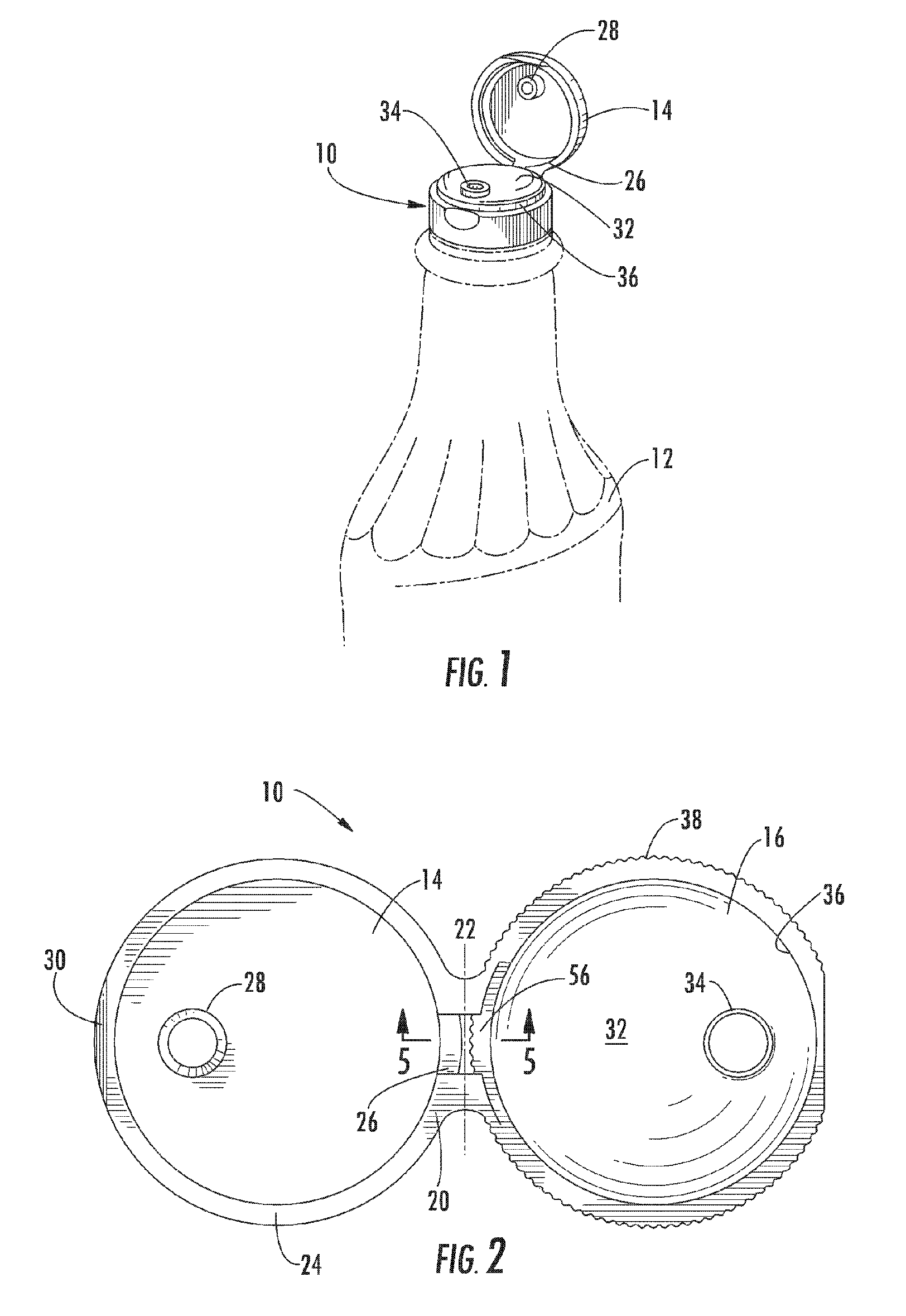
[0050] Referring now to the drawings, FIG. 1 depicts a first embodiment of a dispensing closure constructed in accordance with the principles of the invention. The dispensing closure is generally identified at 10, and is shown secured to the upper end of the neck of container 12. Container 12 may assume the form of a plastic bottle, which may be tilted, and squeezed, to discharge its contents through closure 10.

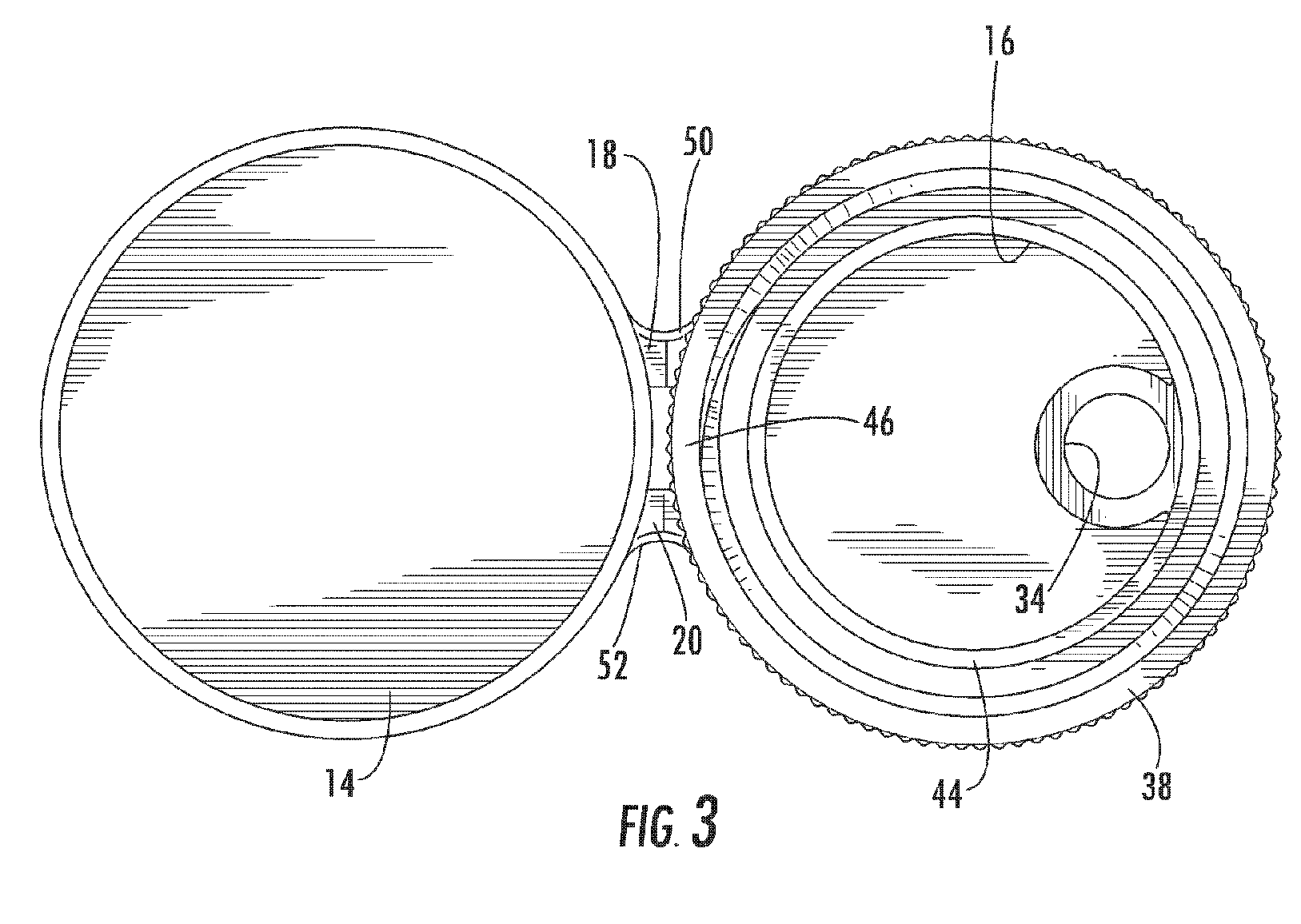
[0051]FIG. 2 shows dispensing closure 10 in its as-molded condition, prior to its securement to container 12. Closure 10 comprises sealing cap 14, a closure body 16, and a pair of hinges 18, 20 that join the sealing cap to the closure body. Sealing cap 14 is pivoted along the center line 22 of the hinges relative to closure body 16.

[0052] Sealing cap 14, as shown in FIGS. 2 and 3, includes an annular flange 24, a camming lug 26 located on flange 24 in proximity to closure body 16, and a depending peg 28. Camming lug 26 is curved, when viewed from above, and follows the cont...


PUM


Abstract

The dispensing closure for a container for dispensing a liquid contained therein, includes a closure body adapted to be mounted on the container. The closure body has an upper wall and a skirt depending downwardly therefrom and a dispensing orifice positioned thereon. A tubular flow modulating structure depends downwardly from the upper wall of the closure body. The tubular flow modulating structure has an inner surface configured and arranged to control the flow of liquid through the dispensing orifice and includes at least one dependent capillary slot. Optionally, the dispensing closure further includes a syneresis capture structure depending downwardly from the upper wall to prevent syneresis fluid from flowing through the dispensing orifice during the dispensing of the liquid contained within the container.

Description

CROSS-REFERENCE TO RELATED APPLICATIONS [0001] This application is a continuation in part from earlier filed U.S. application Ser. No. 10 / 960,179 filed Oct. 7, 2004, which claims priority to earlier filed U.S. Provisional Patent Application No. 60 / 509,523, filed Oct. 9, 2003, and earlier filed U.S. Provisional Application No. 60 / 587,518, filed Jul. 13, 2004. These documents are incorporated herein by reference.BACKGROUND OF THE INVENTION [0002] Dispensing containers are used in a variety of industries for the dispensing of various liquid products. For example, in the beauty industry, products such as shampoo, conditioner, creams and lotions are all packaged in flexible containers having a dispensing closure mounted thereon. Such dispensing containers are also used in the food industry for various condiments, such as ketchup, mayonnaise, and syrups. [0003] One important aspect to the mounting of a dispensing closure in the food industry is sealing of the closure immediately after fil...

Claims


Application Information

Patent Timeline
IPC IPC(8): B65D47/00B65D47/08
CPCB65D47/0809B65D47/0828B65D2251/20B65D2251/1058B65D47/0838B65D47/06B65D47/08B65D2251/10
Inventor SKILLIN, CLIFFORD W.ROMANOV, SERGEY
Owner WESTROCK SLATERSVILLE
Why Eureka
Try Eureka