
In-flight refueling system and method for facilitating emergency separation of in-flight refueling system components

Inactive Publication Date: 2006-01-19
THE BOEING CO
View PDF45 Cites 22 Cited by
  • Summary
  • Abstract
  • Description
  • Claims
  • Application Information

AI Technical Summary

Benefits of technology

[0011] The embodiments of the present invention also provide a method for facilitating the emergency separation of a drogue from an elongate hose wherein the drogue and elongate hose are operably engaged and in fluid communication via a fuse device as part of an in-flight refueling system. The method, according to one embodiment of the present invention, may comprise the steps of: exerting a separating force on the drogue; and disengaging the drogue from elongate hose at the fuse device in response to a separating force exerted on the elongate hose and the drogue, such that the first portion of the elongate hose is separable from the drogue in response to the separating force. According to some method embodiments, the disengaging step may further comprise separating the fuse device into a first segment operably engaged with the elongate hose and a second segment operably engaged with the drogue in response to the separating force experienced thereby. According to other advantageous embodiments, the method of the present invention may further comprise the step of blocking a flow of fuel through the elongate hose so as to prevent the flow of fuel from exiting the elongate hose via the first segment.
[0012] Thus the various embodiments of the in-flight refueling system and method of the present invention provide many advantages that may include, but are not limited to: providing a disengageable and / or separable fluid connection between an elongate hose and a drogue as part of a probe and drogue in-flight refueling system such that the drogue and hose may separate at a predictable point in response to a separating force exerted between a tanker aircraft carrying the elongate hose and drogue and a second aircraft carrying a refueling probe configured to engage the drogue; providing a fuse device that may be easily connected to both the elongate hose and the drogue such that a replacement fuse device may be installed in the probe and drogue in-flight refueling system following an emergency separation of the in-flight refueling system components; and minimizing the chance that the elongate hose may be severed by the separating force so as to minimize the likelihood that a severed portion of the elongate hose may be attached to a refueling probe carried by a second aircraft.

Problems solved by technology

Although in-flight refueling is a relatively common operation, especially for military aircraft, the passage of large amounts of fuel between a first aircraft (serving, for example, as a tanker aircraft) and second aircraft during an in-flight refueling operation may create a potentially dangerous situation, especially if components of the in-flight refueling system separate and / or fail in an uncontrolled manner.
In some cases, however, the catch mechanism within the trailing drogue may malfunction such that the refueling probe may not be disengaged from the trailing drogue without subjecting the hose and / or other in-flight refueling system components to an excessive tension or shear force.
If the guillotine system is used, however, the jettisoned portion of the hose may still hang from the refueling probe of the second aircraft such that a long section of loose hose may be left trailing from the refueling probe.
Such a situation may be extremely dangerous for the operator of the second aircraft, as the remaining section of hose may oscillate uncontrollably with respect to the second aircraft and may strike and shatter a windscreen of the second aircraft or strike and damage a control surface of the second aircraft.
Additionally, if the second aircraft is a jet powered aircraft, the remaining section of hose may be drawn into a jet intake of the second aircraft and damage one or more of the engines of the second aircraft.
This option, however, may also be extremely dangerous, given the precision required to maintain the second aircraft in a position relative to the tanker aircraft so as to safely land the aircraft in unison.
In addition, this option may not be available if, for instance, the in-flight refueling operation is underway far away from an available airfield.
In addition, such a landing may be impossible in cases where the first and second aircraft may have significantly different stall characteristics.

Method used


Image

  • In-flight refueling system and method for facilitating emergency separation of in-flight refueling system components
  • In-flight refueling system and method for facilitating emergency separation of in-flight refueling system components
  • In-flight refueling system and method for facilitating emergency separation of in-flight refueling system components

Examples


Embodiment Construction

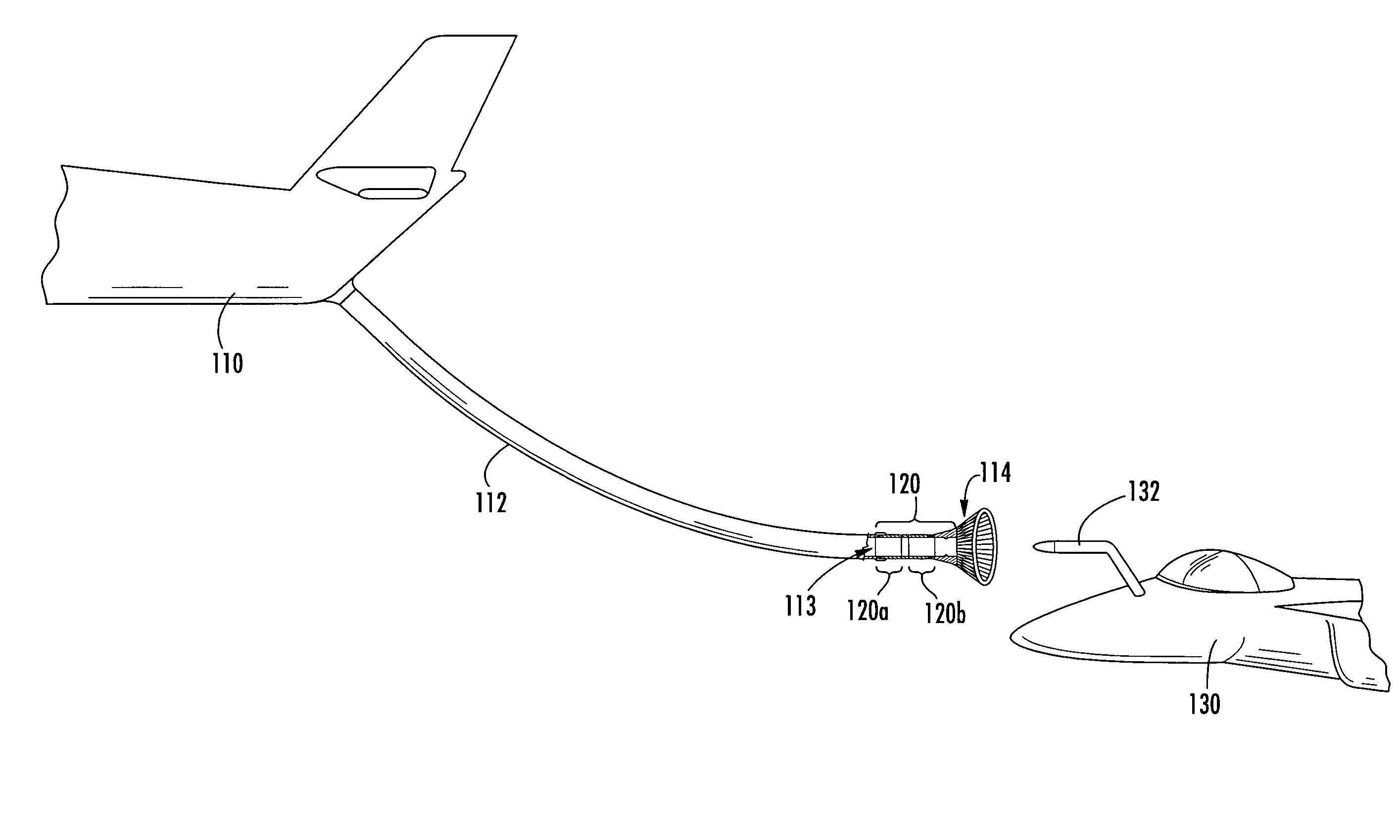
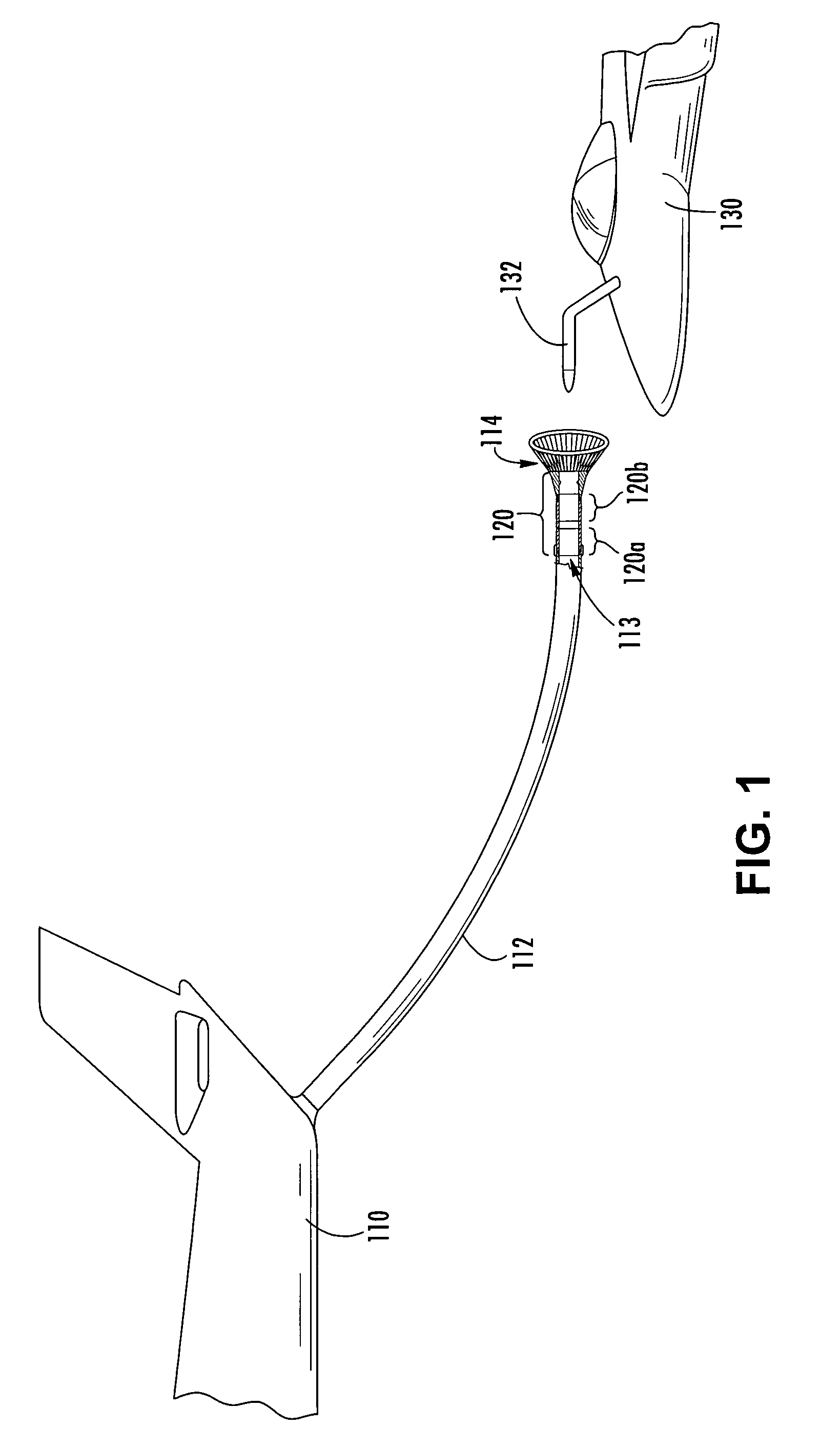
[0021] The present inventions now will be described more fully hereinafter with reference to the accompanying drawings, in which some, but not all embodiments of the invention are shown. Indeed, these inventions may be embodied in many different forms and should not be construed as limited to the embodiments set forth herein; rather, these embodiments are provided so that this disclosure will satisfy applicable legal requirements. Like numbers refer to like elements throughout.

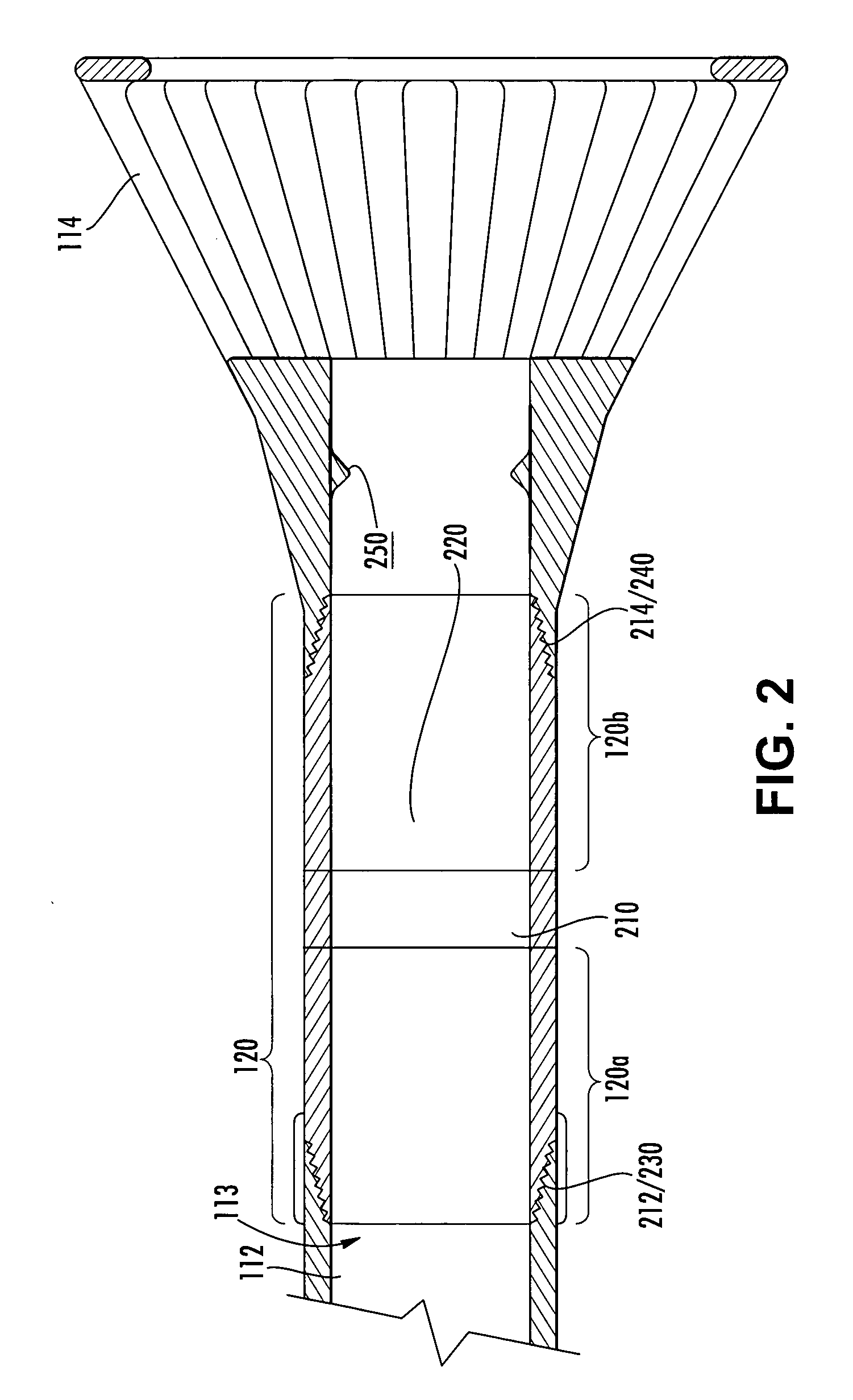
[0022] While the in-flight refueling system and method embodiments of the present invention are described below in the context of a fuse device 120 disposed between an elongate hose 112 and a drogue 114, it should be understood that the embodiments of the present invention may also be utilized to achieve the controlled and predictable separation of a variety of in-flight refueling system components that may be subjected to a separation force during the course of an in-flight refueling operation, including, bu...


PUM


Abstract

An in-flight refueling system and method are provided for facilitating the emergency separation of the components of a probe and drogue in-flight refueling. The in-flight refueling system and method provides a fuse device capable of being installed between, for instance, an elongate hose configured to trail from a tanker aircraft, and a drogue connected to, and in fluid communication with, the elongate hose. The fuse device may be configured to separate in response to a separating force such that the drogue may separate from the elongate hose prior to the exertion of a damaging force, a non-certified force, or an unknown aerodynamic force on the elongate hose, on a probe carried by a second receiver aircraft, or on the tanker aircraft.

Description

FIELD OF THE INVENTION [0001] The present invention relates generally to in-flight refueling of a manned or unmanned aircraft using a probe and drogue in-flight refueling system, and specifically, providing a mechanical fuse device configured to safely and predictably separate two components of an in-flight refueling system. More particularly the mechanical fuse device and method of the present invention provide a mechanical fuse having a known yield point for use in an in-flight refueling system such that should the in-flight refueling system be subjected to tension or shear forces in excess of the yield point of the mechanical fuse device the mechanical fuse may separate in a controlled manner so as to minimize damage to other components of the in-flight refueling system. BACKGROUND OF THE INVENTION [0002] In-flight refueling (or air-to-air refueling) is an important method for extending the range of both manned and unmanned aircraft traveling long distances over areas having no f...

Claims


Application Information

Patent Timeline
IPC IPC(8): B64D39/00
CPCB64D39/04
Inventor SCHROEDER, STEVEN B.
Owner THE BOEING CO
Features
  • Generate Ideas
  • Intellectual Property
  • Life Sciences
  • Materials
  • Tech Scout
  • Unparalleled Data Quality
  • Higher Quality Content
  • 60% Fewer Hallucinations
Learn More