

Thin-film transistors based on tunneling structures and applications
a technology of thin film transistors and tunneling structures, applied in the field of transistors, can solve the problems of the prior art hot hole transistors and the same problems
- Summary
- Abstract
- Description
- Claims
- Application Information
AI Technical Summary
Benefits of technology
Problems solved by technology
Method used
Image

Examples
Embodiment Construction
[0040] The following description is presented to enable one of ordinary skill in the art to make and use the invention and is provided in the context of a patent application and its requirements. Various modifications to the described embodiments will be readily apparent to those skilled in the art and the generic principles herein may be applied to other embodiments. Thus, the present invention is not intended to be limited to the embodiment shown but is to be accorded the widest scope consistent with the principles and features described herein.
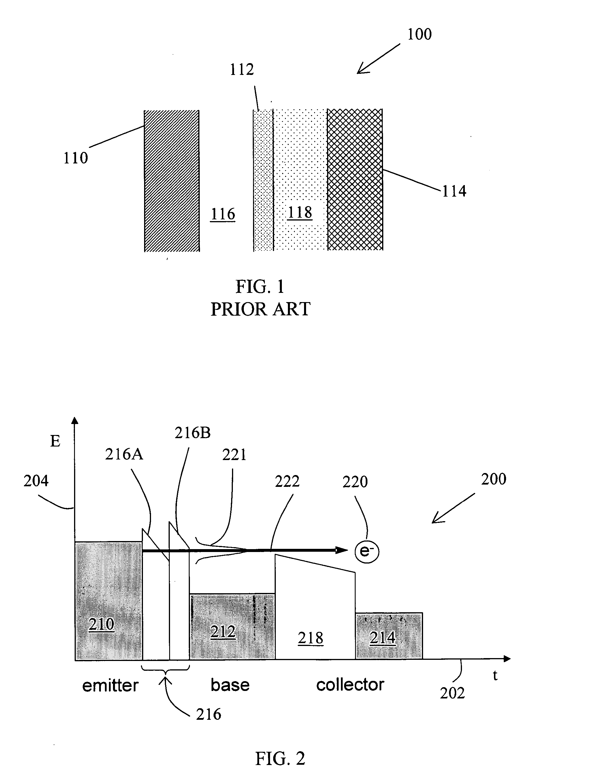
[0041] While the M-I-M-I-M thin film transistor structure has been analyzed since around 1960, a commercially useful device has not been demonstrated by others to date. Recent advancements in the state of materials processing and understanding, device fabrication and device modeling techniques contribute positively to the possibility of achieving a well-controlled M-I-M-I-M thin-film transistor and understanding its operation. Furthermore,...
PUM
 Abstract
Description
Claims
Application Information